241
Communication operation and setting
(9) Signal loss detection (Pr. 539 Modbus-RTU communication check time interval)
If a signal loss (communication stop) is detected between the inverter and master as a result of a signal loss
detection, a communication error (E.SER) occurs and the inverter output is shut off.
· When the setting is "9999", communication check (signal loss detection) is not made.
· When the setting value is "0", monitor, parameter read, etc. can be performed. However, a communication error
(E.SER) occurs as soon as the inverter is switched to the Network operation mode.
· A signal loss detection is made when the setting is any of "0.1s to 999.8s". To make a signal loss detection, it is
necessary to send data from the master within the communication check time interval. (The inverter makes
communication check (clearing of communication check counter) regardless of the station number setting of the data
sent from the master.)
· Communication check is started from the first communication after switching to the Network operation mode (use Pr.
551 PU mode operation command source selection to change).
· Communication check time of query communication includes data absence time (3.5 byte).
Since this data absence time differs according to the communication speed, make setting considering this absence
time.
REMARKS
When using RS-485 terminal communication, inverter behaviour at fault occurrence is different depending on Pr. 502 Stop mode
selection at communication error setting. (Refer to page 211)
Operation mode
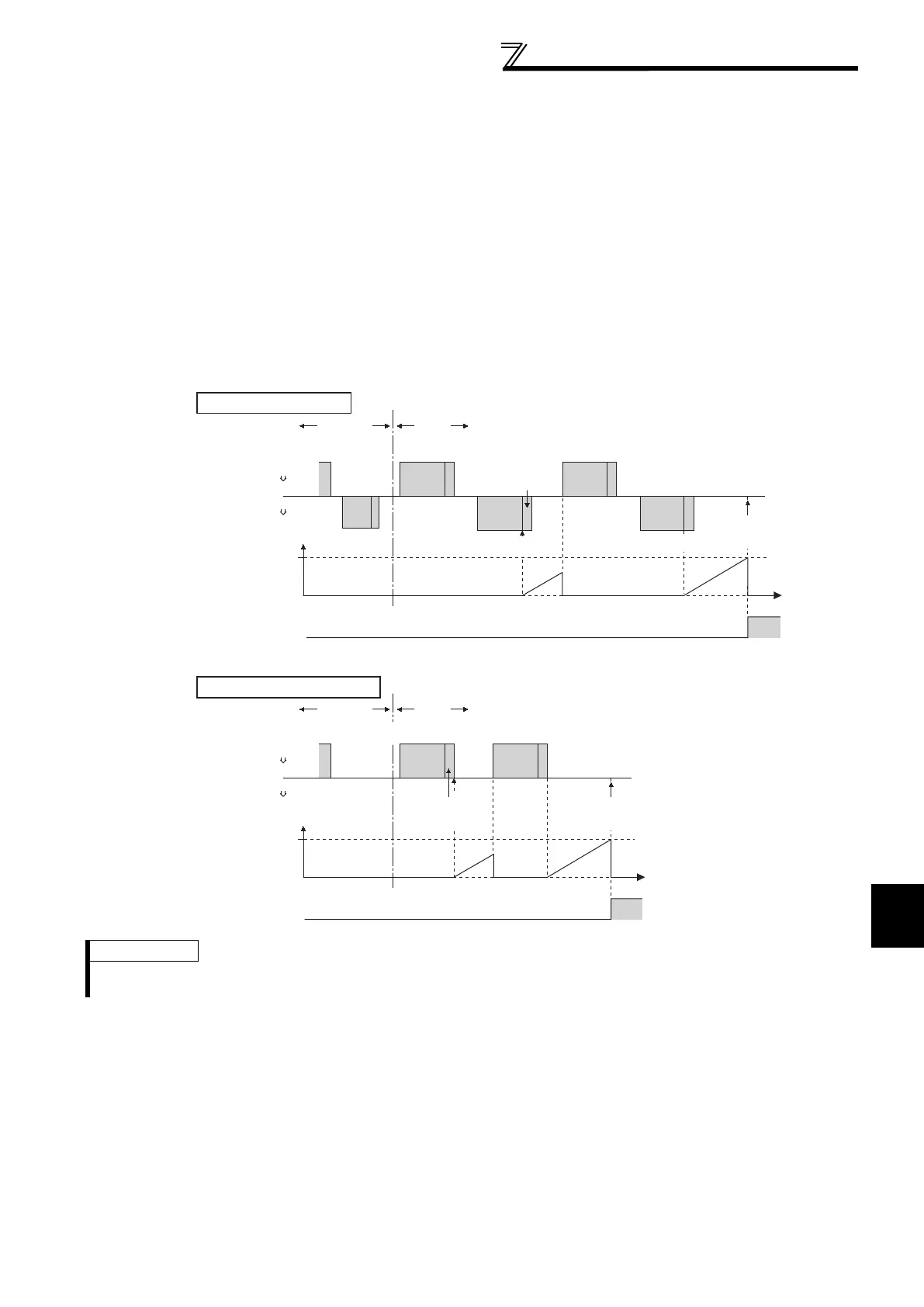
Example: RS-485 terminal communication, Pr. 539 = "0.1 to 999.8s"
External NET
Check start
Tim
Inverter (slave)
Inverter (slave)
Communication
check counter
Pr.539
Programmable controller (master)
Programmable controller (master)
Query Message 1 Query Message 2
Data absence time
(3.5 bytes or more)
Response Message1
Response Message2
Fault
(E.SER)
Operation mode External NET
Check start
Time
Inverter (slave)
Inverter (slave)
Communication
check counter
Pr.539
Programmable controller (master)
Programmable controller (master)
Query Message 2
Fault
(E.SER)
Data absence time
(3.5 bytes or more)
Query Message 1
Query communication
Broadcast communication
ALM
ON
ALM
ON

 Loading...


