249
Communication operation and setting
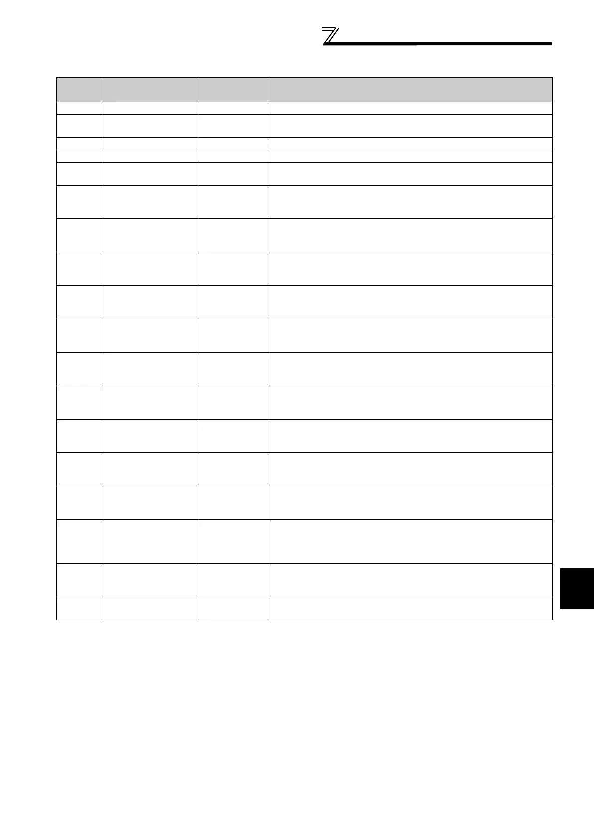
BINARY VALUE
*1 R: Read only W: Read/Write (Commandable values not supported) C: Read/Write (Commandable values supported)
*2 The following signals cannot be controlled by the network: Jog operation, automatic restart after instantaneous power failure, start self-holding
and reset. Therefore control input instruction JOG, STOP, RES, and CS are invalid in the initial status. When using Control input instruction JOG,
STOP, RES, and CS, change the signals with Pr. 185, Pr. 186, Pr. 188, Pr. 189 (input terminal function selection). (Refer to page 117) (Reset is
available with ReinitializeDevice. )
*3 If communication speed command source is except for NET, the setting value can be written, but not to be applied.
Object
Identifier
Object Name
Present Value
Access Type
*1
Description
0 Inverter running R Represents inverter running (RUN signal) status.
11
Inverter operation
ready
R Represents inverter operation ready (RY signal) status.
98 Alarm output R Represents alarm output (LF signal) status.
99 Fault output R Represents fault output (ALM signal) status.
200
Inverter running
reverse
R Represents inverter reverse running status.
300
Control input instruction
AU
C
Controls the function assigned to terminal AU.
Setting 1 of this object turns ON the signal assigned to Pr. 184 AU terminal
function selection.
301
Control input instruction
RT
C
Controls the function assigned to terminal RT.
Setting 1 of this object turns ON the signal assigned to Pr. 183 RT terminal
function selection.
302
Control input instruction
RL
C
Controls the function assigned to terminal RL.
Setting 1 of this object turns ON the signal assigned to Pr. 180 RL terminal
function selection.
303
Control input instruction
RM
C
Controls the function assigned to terminal RM.
Setting 1 of this object turns ON the signal assigned to Pr. 181 RM terminal
function selection.
304
Control input instruction
RH
C
Controls the function assigned to terminal RH.
Setting 1 of this object turns ON the signal assigned to Pr. 182 RH terminal
function selection.
305
Control input instruction
JOG
*2
C
Controls the function assigned to terminal JOG.
Setting 1 of this object turns ON the signal assigned to Pr. 185 JOG
terminal function selection.
306
Control input instruction
MRS
C
Controls the function assigned to terminal MRS.
Setting 1 of this object turns ON the signal assigned to Pr. 187 MRS
terminal function selection.
307
Control input instruction
STOP
*2
C
Controls the function assigned to terminal STOP.
Setting 1 of this object turns ON the signal assigned to Pr. 188 STOP
terminal function selection.
308
Control input instruction
RES
*2
C
Controls the function assigned to terminal RES.
Setting 1 of this object turns ON the signal assigned to Pr. 189 RES terminal
function selection.
309
Control input instruction
CS
*2
C
Controls the function assigned to terminal CS.
Setting 1 of this object turns ON the signal assigned to Pr. 186 CS terminal
function selection.
400 Run/Stop C
Controls start/stop command. Start command is written after Speed scale
is applied.
*3
1: Run
0: Stop
401 Forward/Reverse C
Controls forward/reverse rotation.
*3
1: Reverse rotation
0: Forward rotation
402 Fault reset C
Clears fault output status.
(Release of an inverter fault without inverter reset is available.)

 Loading...


