266
PID control
<Set point input calibration>
1) Setting with terminal 2 input
1. Apply the input voltage of 0% set point setting (e.g. 0V) across terminals 2 and 5.
2. Enter in C2 (Pr. 902) the frequency which should be output by the inverter at the deviation of 0% (e.g. 0Hz).
3. In C3 (Pr. 902), set the voltage value at 0%.
4. Apply the voltage of 100% set point (e.g. 5V) to across terminals 2 and 5.
5. Enter in Pr. 125 the frequency which should be output by the inverter at the deviation of 100% (e.g. 50Hz).
6. In C4 (Pr. 903), set the voltage value at 100%.
2) Setting with Pr. 133
When both or one of C42 (Pr. 934) and C44 (Pr. 935) is "9999".
For the set point, set a % converted value in the range of 0 to 100%.
When both of C42 (Pr. 934) and C44 (Pr. 935) "9999".
For the set point, set PID coefficient, which corresponds with 0 to 100%.
<Measured value calibration>
1) When both or one of C42 (Pr.934) and C44 (Pr.935) is "9999".
1. Apply the input current of 0% measured value (e.g. 4mA) across terminals 4 and 5.
2. Make calibration using C6 (Pr. 904).
3. Apply the input current of 100% measured value (e.g. 20mA) across terminals 4 and 5.
4. Make calibration using C7 (Pr. 905).
2) When both of C42 (Pr.934) and C44 (Pr.935) "9999".
1. Apply the input current of 0% measured value (e.g. 4mA) across terminals 4 and 5.
2. Set PID display value at 0% measured value (example: 15(C)) to C42 (Pr. 934) , and calibrate C43 (Pr. 934).
3. Apply the input current of 100% measured value (e.g. 20mA) across terminals 4 and 5.
4. Set PID display value at 100% measured value (example: 35(C)) to C44 (Pr. 935), and calibrate C45 (Pr. 935).
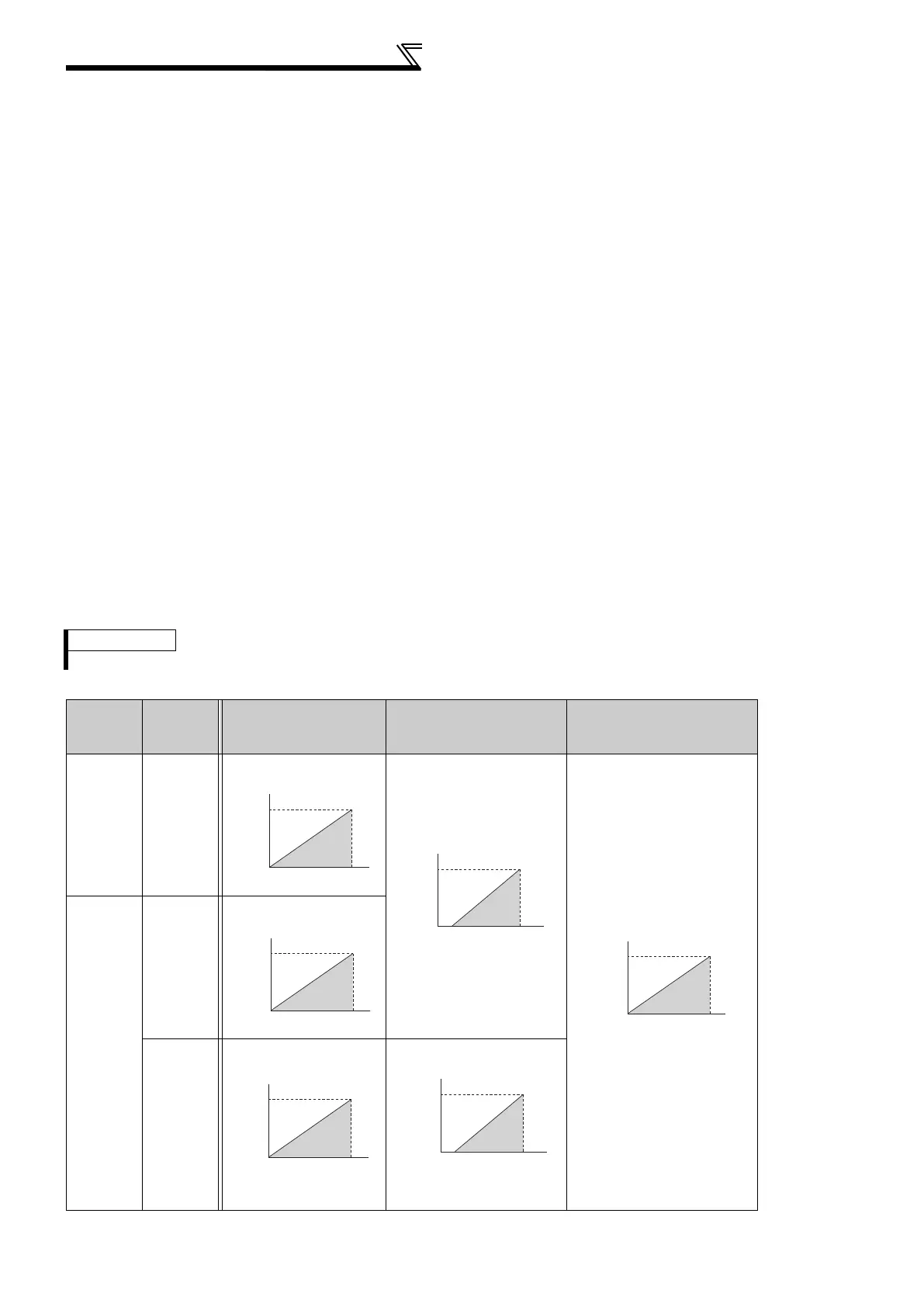
The results of the above calibration are as shown below:
REMARKS
The frequency set in C5 (Pr. 904) and Pr. 126 should be the same as set in C2 (Pr. 902) and Pr. 125.
Pr. 133
Setting
Pr. 934,
Pr. 935
Setting
Set Point Setting
Measured Value
(Terminal 4)
Manipulated Variable
9999 —
(Terminal 2)
Other than
9999
Both or one
is 9999
(Pr.133)
Other than
9999
(Pr.133)
Set PID coefficient
corresponding with 0 to 100%.
100
0
0
5 (V)
Set point signal input
Set point
(%)
100
0
0
20
C7(Pr.905)
(mA)
Measured value
input signal
Measured
Value
(%)
4
C6(Pr.904)
60
(Pr.125)
0
C2(Pr.902)
0
100
Deviation(%)
Manipulated
Variable(Hz)
100
0
C5(Pr.904)
Pr.126
Set point setting
Set point
(%)
100
0
C42(Pr.934)
C44(Pr.935)
Set point
(%)
100
0
0
20
C45(Pr.935)
(mA)
Measured value
input signal
Measured
value
(%)
4
C43(Pr.934)

 Loading...


