308
Useful functions
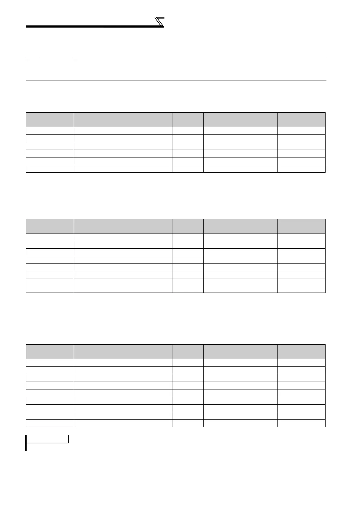
(4) List of automatically-set parameters
The following tables show which parameters are changed in each of the automatic parameter settings.
Normal PID setting
When the PID display increments are not extended
* In this setting, the dedicated parameter list is not displayed while FR-PU07-01 is connected. (However, when another setting is made to activate the PID
control, the list may be displayed according to the setting. (Refer to page 315 for the details. )
Extended PID display increment setting
When the PID display increments are extended
* Pr. 934 and Pr. 935 settings affect displays of other parameters. Perform automatic setting of the extended PID display increments first. By doing this, the
dedicated parameter list will be displayed when FR-PU07-01 is connected. In the initial status, the Pr. 999 setting is applied for the display. After the setting, the
Pr. 934 and Pr. 935 settings are applied.
The 3-line monitor is displayed first after the automatic setting while a parameter unit (FR-PU07(-01)) is connected.
GOT initial setting (PU connector) (Pr. 999 = "10")
CAUTION
If the automatic setting is performed with Pr. 999 or the parameter setting mode, the listed settings including the changed
parameter settings (changed from the initial setting) will be automatically changed. Before performing the automatic setting,
confirm that changing the listed parameters will not cause any problem.
Parameter Name
Initial
value
Automatically set to Refer to page
759 PID unit selection 9999 9999 316
774 PU/DU monitor selection 1 9999 9999 318
775 PU/DU monitor selection 2 9999 9999 318
776 PU/DU monitor selection 3 9999 9999 318
934 PID display bias coefficient 9999 9999 268
935 PID display gain coefficient 9999 9999 268
Parameter Name
Initial
value
Automatically set to Refer to page
759 PID unit selection 9999 4 316
774 PU/DU monitor selection 1 9999 52 318
775 PU/DU monitor selection 2 9999 53 318
776 PU/DU monitor selection 3 9999 54 318
934 PID display bias coefficient 9999 0 268
935 PID display gain coefficient 9999 100 268
— 3-line monitor start setting 9999
The 3-line monitor is displayed
first.
315
Parameter Name
Initial
value
Automatically set to Refer to page
79 Operation mode selection 0 1 190
118 PU communication speed 192 192 209
119 PU communication stop bit length 1 10 209
120 PU communication parity check 2 1 209
121 Number of PU communication retries 1 9999 209
122 PU communication check time interval 9999 9999 209
123 PU communication waiting time setting 9999 0ms 209
124 PU communication CR/LF selection 1 1 209
340 Communication startup mode selection 0 0 198
REMARKS
Always perform an inverter reset after the initial setting.
 Loading...


