EasyManuals Logo

Mitsubishi M80 series User Manual

Mitsubishi M80 series
648 pages
To Next Page IconTo Next Page
To Previous Page IconTo Previous Page
Page #238 background imageLoading...
Page #238 background image
M800S/M80/E80 Series Connection and Setup Manual
5 Installation
201
IB-1501269-J
5.3 Unit Installation
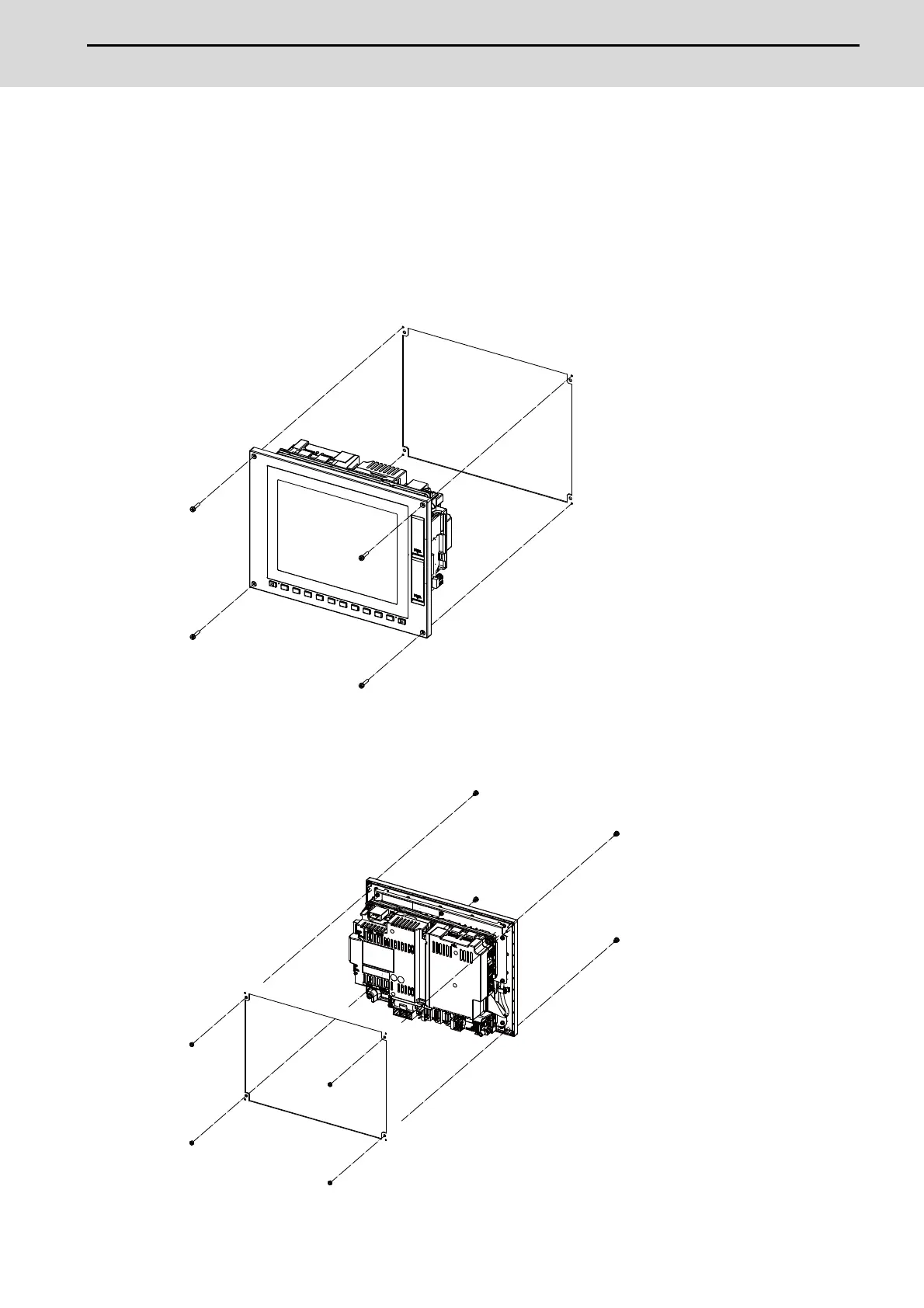
5.3.1 Display Unit
Mount the display unit with the prescribed number of fixing screws.
(Note) Refer to "General Specifications: Display Unit" for the panel cut dimension drawing and the screw hole
position.
[FCU8-DU121 (8.4-type display unit)]
- Fixed on the front side
Fixing screw: Cheese head screw M3 (4 pcs).
(Fixing screws are provided with the unit.)
- Fixed on the back side
Fixture: M3 nut (4 pcs).
(4 pcs of the screw caps (a) are provided with the unit.)
(a)

Table of Contents

Questions and Answers:

Question and Answer IconNeed help?

Do you have a question about the Mitsubishi M80 series and is the answer not in the manual?

Mitsubishi M80 series Specifications

General IconGeneral
TypeCNC Control Unit
Power Supply24V DC
InterpolationLinear, circular, helical
FieldbusCC-Link
Operating Temperature0 to 45°C
InterfaceUSB, RS-232
ProcessorRISC processor
EthernetYes (100BASE-TX/10BASE-T)

Related product manuals