M800S/M80/E80 Series Connection and Setup Manual
17 Setting the Hardware
393
IB-1501269-J
17.6 Connecting and Setting the Remote I/O Unit
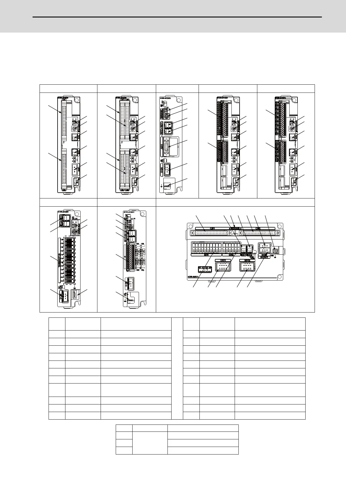
17.6.1 Outline of the Remote I/O Unit
The specification varies for each remote I/O unit. Each unit has one or two rotary switch(es) for unit No. setting, which
links the device Nos. (with X/Y).
FCU8-DX220 FCU8-DX230 / DX231 FCU8-DX202 FCU8-DX213 / DX213-1 FCU8-DX654 / DX654-1
FCU8-DX408 FCU8-DX409 FCU8-DX651
No.
Connector
name
Function No.
Connector
name
Function
(1) CJ31 Machine signal input (12) SDO2 Safety relay output
(2) CJ32 Machine signal output (13) RIO1 Remote I/O 2.0 communication
(3) CJ33 Machine signal input (14) RIO2 Remote I/O 2.0 communication
(4) CJ34 Machine signal output (15) DCIN 24VDC input
(5) CJ35 Machine signal input (16) DCOUT 24VDC output
(6) CJ36 Machine signal output (17) FG FG terminal
(7) SDI Safety machine signal input (18) FG FG terminal (M4 screw)
(8) SDO Safety machine signal output (19) AIO1
Analog input
Analog output
(9) SDI1 Safety DI input (20) THERMISTOR Thermistor input
(10) SDI2 Safety DI input (21) AI Multi-analog input
(11) SDO1 Safety relay output
No. Switch name Function
(s1)
STATION No.
Station No. group setting switch
(s2) Station No. setting switch
(s3) Station No. setting switch
(1)
(2)
(13)
(14)
(15)
(s2)
(s1)
(17)
(1)
(2)
(3)
(4)
(13)
(14)
(15)
(s2)
(s1)
(17)
(13)
(14)
(15)
(s2)
(s1)
(17)
(19)
(5)
(6)
(13)
(14)
(15)
(s2)
(s1)
(17)
(7)
(8)
(13)
(14)
(15)
(s2)
(s1)
(17)
(13)
(15)
(14)
(s2)
(s1)
(17)
(20)
(17)
(15)
(14)
(21)
(s2)
(s1)
(13)
(9) (11)
(13)
(15) (18)(2)(1)
(10) (12)
(14)
(s3)
(16)

 Loading...


