M800S/M80/E80 Series Connection and Setup Manual
15 Cable
342
IB-1501269-J
15.1 Symbols for Writing Cable Drawings
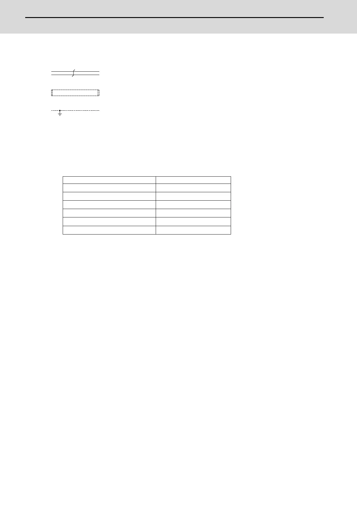
(1) indicates twisted pair.
(2) indicates the shield sheath.
(3) indicates shield clamping to the grounding plate.
(4) In the cable drawings, the partner of the twisted pair cable is given a priority, so please be aware that the pin No. of
the connectors at both ends are not necessarily in sequential order.
(5) Equivalent parts can be used for the connector, contact and wire material.
(6) The tolerances of the cables provided by MITSUBISHI are as follows:
Cable length (mm) Tolerances (mm)
~ 600
±30
601 ~ 1000
±50
1001 ~ 5000
±100
5001 ~ 10000
±150
10001 ~ 15000
±200
15001 ~ 20000
±300

 Loading...


