M800S/M80/E80 Series Connection and Setup Manual
7 Connection of Control Unit
238
IB-1501269-J
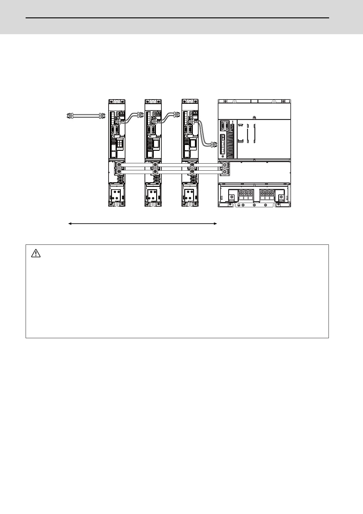
(3) When using the additional axis drive unit by supplying power (L+, L-) from MDS-EM/EMH unit
The power (L+, L-) can be supplied to the additional axis drive unit by using the power supply part which is built into
MDS-EM/EMH.
CAUTION
1. There is a limit to the combination of the drive unit.
Refer to "7.3 Selection of the Additional Axis Drive Unit" in "MDS-EM/EMH Series Specifications Manual".
2. When using the additional axis drive unit by supplying power (L+, L-) from MDS-EM/EMH unit, install the optical
communication cables in a manner that makes MDS-EM/EMH unit the final axis. Failure to observe this could
lead to damage unit.
3. When installing the additional axis unit, install the spindle drive unit with maximum capacity adjacent to the
MDS-EM/EMH-SPV3, and connections for other drive units should be such that the total TE2 wiring length is
800mm or less.
MDS-EM-SPV3
MDS-E-V1 MDS-E-SP2 MDS-E-SP
TE2
The optical communication cables from the NC to the
final drive unit must be within 30m.
Optical
communication
cable
5th axis 8th axis6th/7th axis
Servo:2nd/3rd/4th axis
Spindle:1st axis
When using MDS-EM drive unit together with MDS-E

 Loading...


