M800S/M80/E80 Series Connection and Setup Manual
7 Connection of Control Unit
254
IB-1501269-J
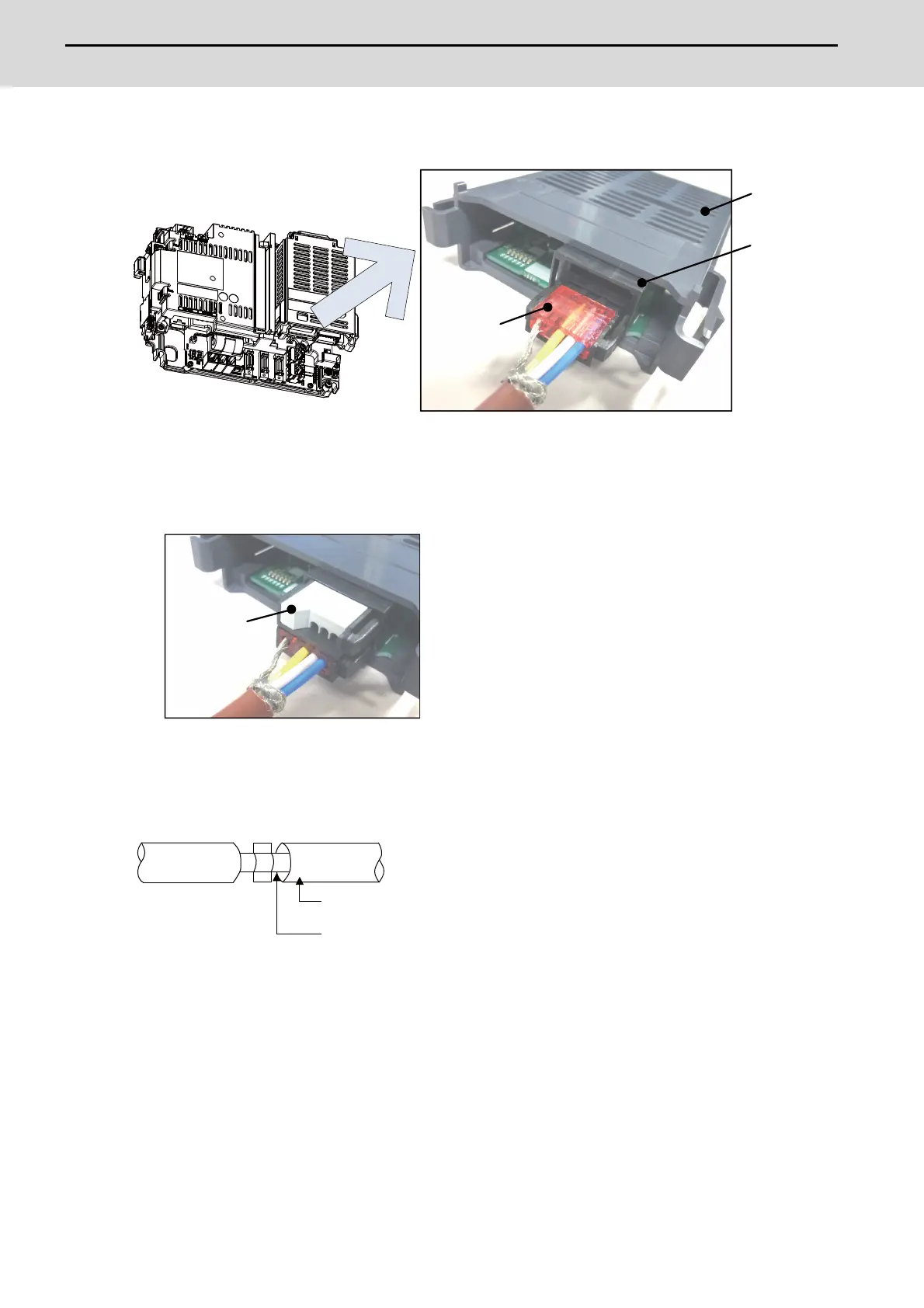
(5) Insert the CC-Link cable into the connector of CC-Link unit.
(Note) Connector of CC-Link unit is two-step structure. It is not different even if attach the cable to
whichever.
(6) Insert the terminator to the connector of CC-Link unit as in the figure.
In the final station, the terminator connector is required.
[Noise countermeasures of CC-Link dedicated cable]
When the CC-Link expansion unit is being used, expose the cable by removing a part of the cable sheath and make
sure to use the shield clamp for the exogenous noise countermeasure.
Refer to "4.4 Shield connection to ground" of CC-Link cable wiring manual (published by CC-Link partner
association) for shield wire grounding for CC-Link dedicated cable.
<Related item>
Shield clamp fitting: "EMC Installation Guidelines: EMC Countermeasure Parts: Shield Clamp Fitting"
Control unit
Connector of
CC-link unit
CC-link cable
CC-Link
expansion unit
Shield
CC-Link dedicated cable

 Loading...


