M800S/M80/E80 Series Connection and Setup Manual
10 Connection of Remote I/O Unit
317
IB-1501269-J
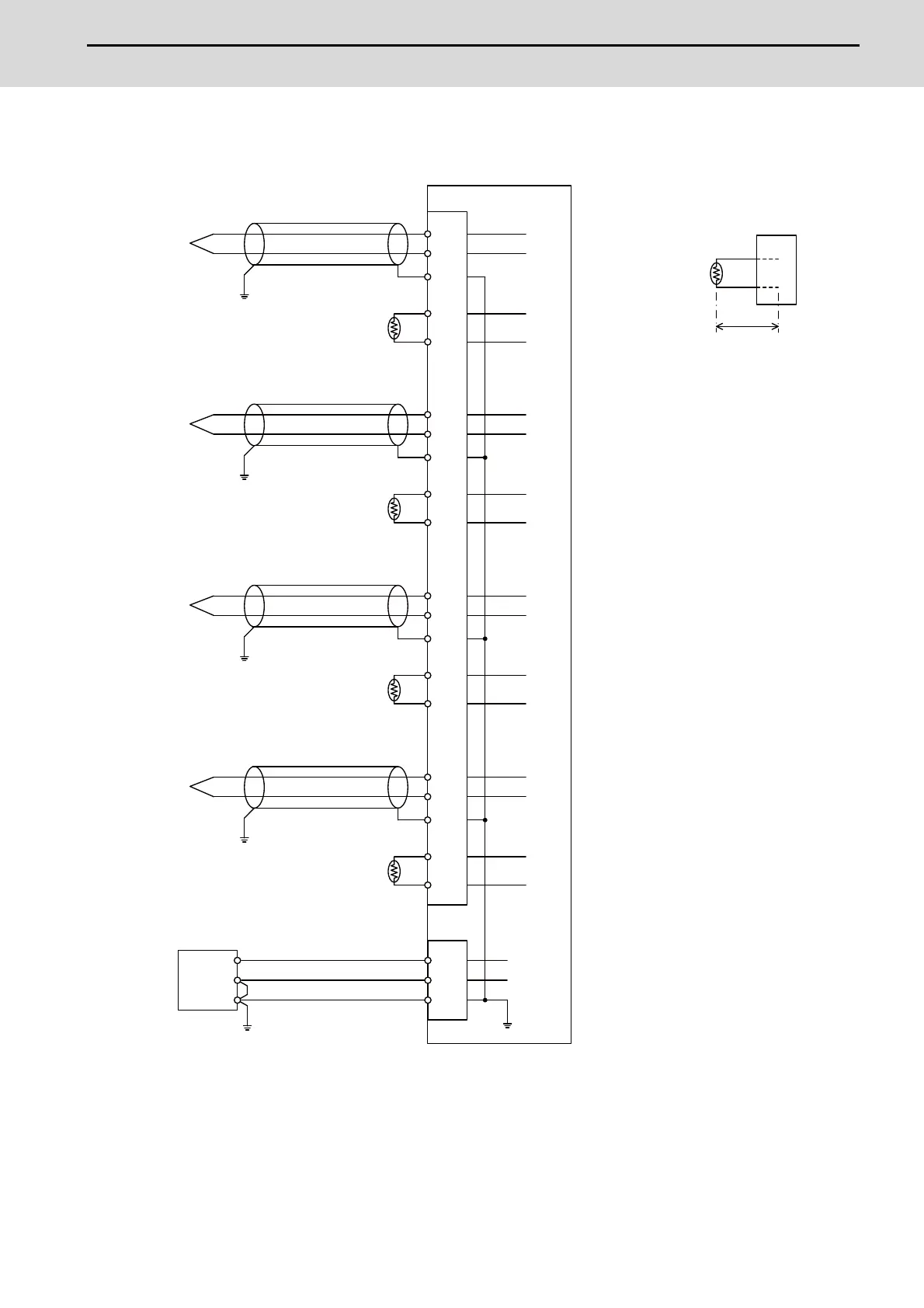
(c) Connecting with the thermocouple input signal
- Connect the shield to FG pin of AI connector. Ground the thermocouple tip side, too.
- Do not connect or disconnect the cables between units while the power is ON.
- Keep the lead length of cold junction compensation resistor as short as possible (2 cm or shorter as a guide).
AI
3
5
1
FCU8-DX409
4
6
(Pt100)
FG
(Pt100)
AI
CJ+
CJ-
V+
V-
CJ+
CJ-
CH1
7
9
12
8
10
(Pt100)
FG
V+
V-
CJ+
CJ-
CH2
15
17
13
16
18
(Pt100)
FG
V+
V-
CJ+
CJ-
CH3
19
21
24
20
22
(Pt100)
FG
V+
V-
CJ+
CJ-
CH4
0V
FG
1
2
3
DCIN
0V
FG
+24V
FG
FG
FG
FG
24VDC(+)
Thermocouple
Cold junction compensation resistor
Set the lead length 2cm or
shorter including the length to
insert to AI connector. (As a guide)
Shield
Cold junction
compensation
resistor
2cm or shorter
Cold junction compensation resistor
Shield
Thermocouple
Cold junction compensation resistor
Shield
Thermocouple
Cold junction compensation resistor
Shield
Thermocouple
Stabilized power supply
 Loading...


