5 - 112
Chapter 5 Data Used for Positioning Control
5.6 List of monitor data
The setting items of the monitor data are explained in this section.
• Guide to buffer memory address
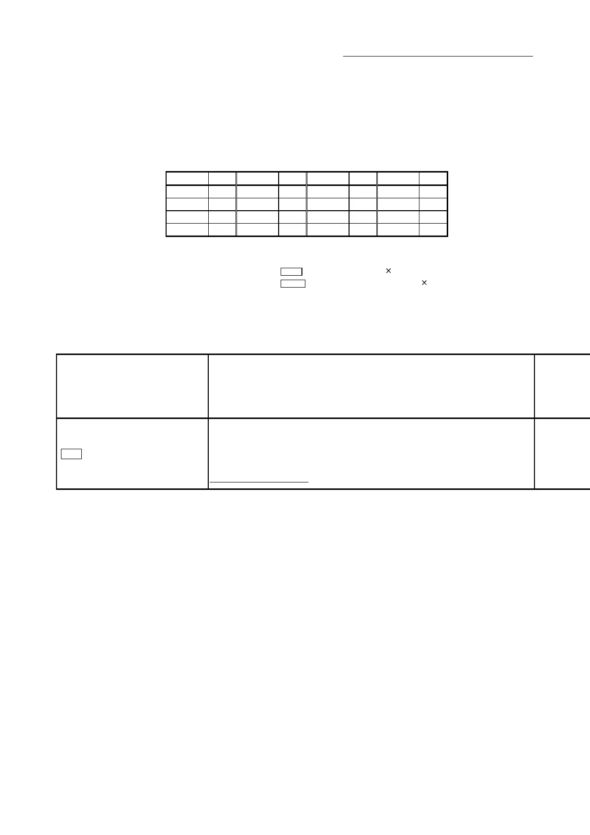
In the buffer memory address, "n" in "2406+100n", etc. indicates a value
corresponding to axis No. such as the following table.
Axis No. n Axis No. n Axis No. n Axis No. n
1 0 5 4 9 8 13 12
2 1 6 5 10 9 14 13
3 2 7 6 11 10 15 14
4 3 8 7 12 11 16 15
(Note-1): Calculate as follows for the buffer memory address corresponding to each axis.
(Example) For axis No. 16
2406+100n (
Md.23 Axis error No.)=2406+100 15=3906
2494+100n (
Md.123 Torque during command)=2494+100 15=3994
(Note-2): The range from axis No.1 to 2 (n=0 to 1) is valid in the QD77MS2.
(Note-3): The range from axis No.1 to 4 (n=0 to 3) is valid in the QD77MS4.
5.6.1 System monitor data
Storage item Storage details
Md.1
In test mode flag
Whether the mode is the test mode from the GX Works2 or not is stored.
•
When not in test mode : OFF
•
When in test mode : ON
Refresh cycle: Immediate

 Loading...


