2 - 2
Chapter 2 System Configuration
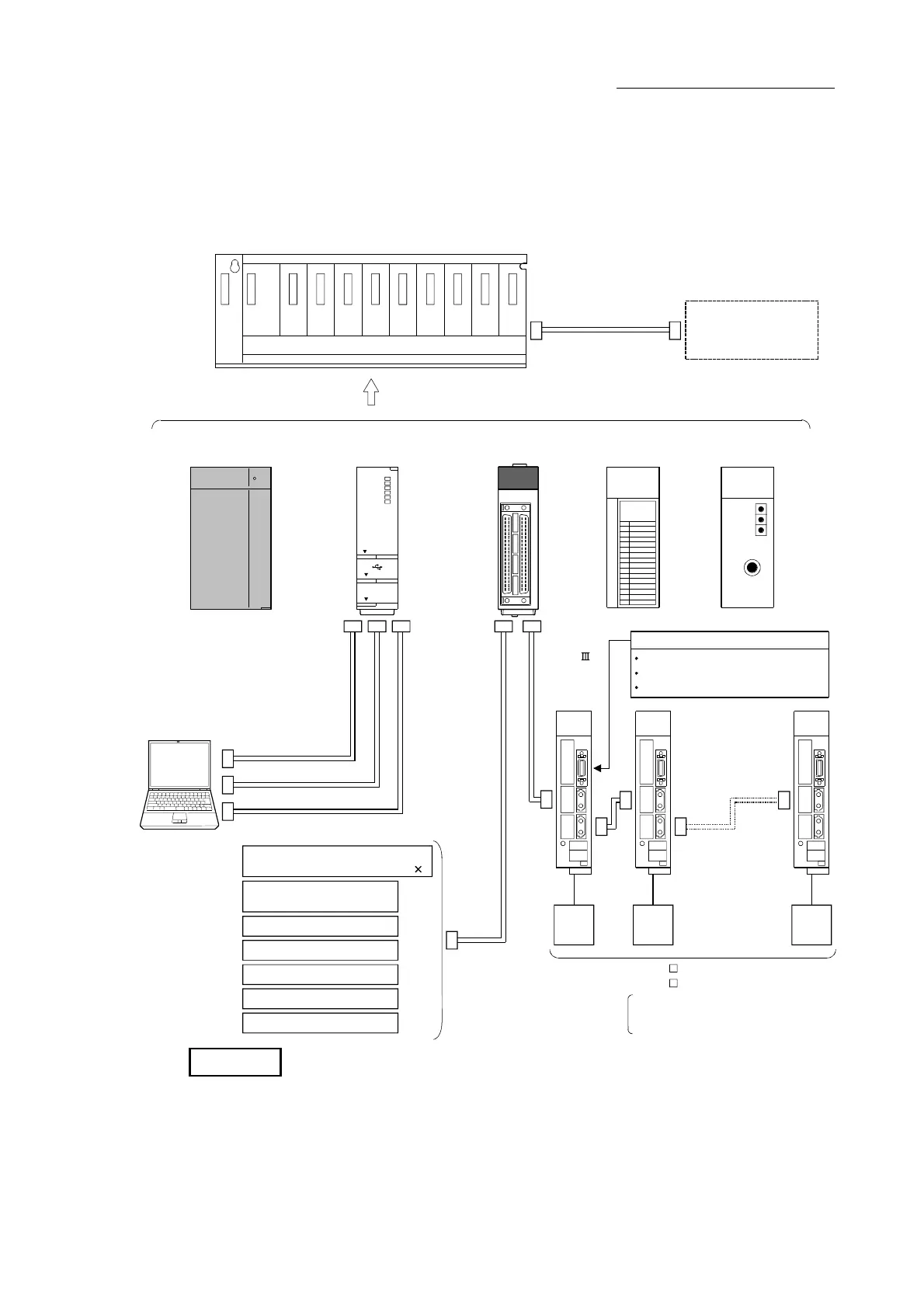
2.1 General image of system
The general image of the system, including such as the QD77MS, PLC CPU and
peripheral devices is shown below.
Expansion system
Expansion cable
Servo
motor
Servo
motor
Servo
motor
Personal compute
Power supply module CPU module
QD77MS
SSCNET
cable
External input
signal cable
USB cable
Ethernet cable
QD77MS4
RUN
ERR.
AX1
AX4
AX2
AX3
QD77MS4
AX2
AX1
AX4
AX3
Main base unit
RS-232 cable
External input signals of servo amplifier
Upper stroke limit
Lower stroke limit
Near-point dog
I/O module
Intelligent function
module
Upper stroke limit (4 points)
Forced stop input (24VDC)
Manual pulse generator
/Incremental synchronous encoder
1
External command signal
/Switching signal (4 points)
Lower stroke limit (4 points)
Near-point dog signal (4 points)
Stop signal (4 points)
MR-J3(W)- B model Servo amplifier
MR-J4(W)- B model Servo amplifier
QD77MS2 :Up to 2 axes
QD77MS4 :Up to 4 axes
QD77MS16 :Up to 16 axes
REMARK
(Note-1): Refer to Section "2.3 Applicable system" for the CPU modules that can be used.
(Note-2): Refer to the CPU module User's Manual for the base units that can be used.

 Loading...


