14 - 10
Chapter 14 Common Functions
14.5 External I/O signal logic switching function
This function switches the signal logic according to the external equipment connected
to the QD77MS, "
Cd.44 External input signal operation device" or the external input signal
(upper/lower limit switch, near-point dog) of the servo amplifier.
For the system in which b-contact, upper limit switch, and lower limit switch are not
used, the parameter logic setting can be controlled without wiring if it is changed to a
"positive logic".
When the upper limit switch, and lower limit switch are used, ensure to use them with
negative logic (b-contact).
The details shown below explain about the "External I/O signal logic switching
function".
[1] Parameter setting details
[2] Precautions on parameter setting
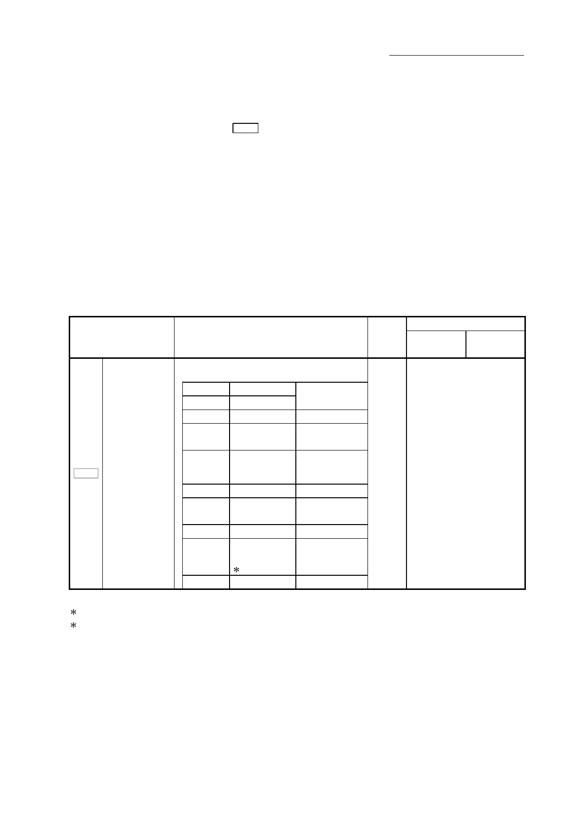
[1] Parameter setting details
To use the "External I/O signal logic switching function", set the parameters
shown in the following table.
Buffer memory address
Setting item Setting details
Factory-
set initial
value
QD77MS2
QD77MS4
QD77MS16
• Selection of logic of signals input from external
device to QD77MS
b0 Lower limit
b1 Upper limit
0: Negative logic,
1: Positive logic
b2 Not used Set "0".
b3 Stop signal
0: Negative logic,
1: Positive logic
b4
External
command/
switching signal
0: Negative logic,
1: Positive logic
b5 Not used Set "0".
b6
Near-point dog
signal
0: Negative logic,
1: Positive logic
b7 Not used Set "0".
b8
Manual pulse
generator input
1
0: Negative logic,
1: Positive logic
Pr.22
Input signal logic
selection
b9 to b15 Not used Set "0".
0 31+150n
n: Axis No.-1
1: Only the value specified against the axis 1 is valid for the logic selection of manual pulse generator input (b8).
: Refer to Section 5.2 "List of parameters" for the information on detail settings.

 Loading...


