3 - 30
Chapter 3 Specifications and Functions
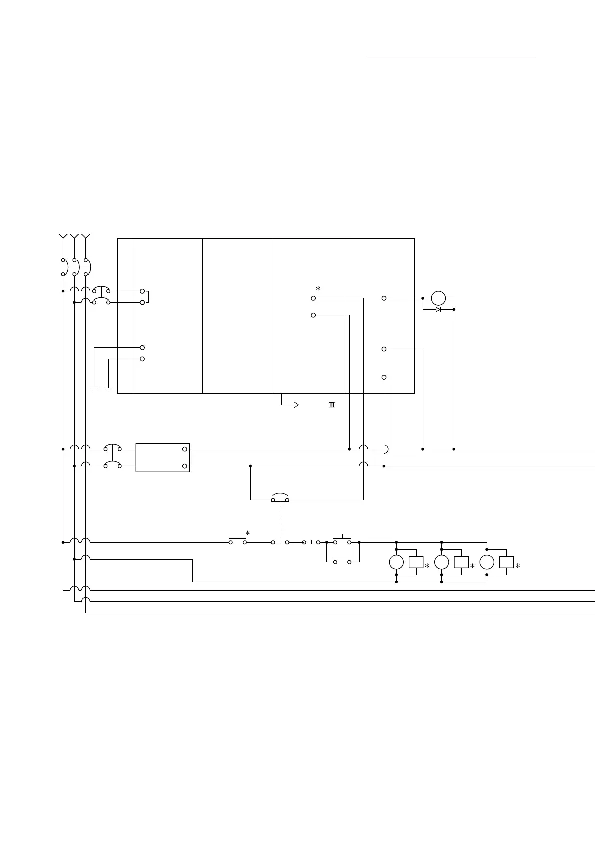
3.5 External circuit design
Configure up the power supply circuit and main circuit which turn off the power supply
after detection alarm occurrence and servo forced stop. When designing the main
circuit of the power supply, make sure to use a circuit breaker (MCCB).
The outline diagrams of the internal circuits for the external device connection interface
are shown below.
(1) Example when using the forced stop of the QD77MS
CP2
+24V
24G
24VDC
Power
supply
MC1 to 3
Ready
ON
Operation
OFF
Emergency Stop
EMG
Alarm
Ra1
1
3-phase
200 to 230VAC
CP1
MCCB1
RST
INPUT
100-240VAC
FG
LG
Power Supply
Q61P
QnCPU
PLC CPU
QD77MS
EMI
EMI.COM
Forced stop
Output module
QY41P
Ra1
Yn
COM
12/24VDC
SSCNET (/H)
Simple Motion
module
5
7
Surge suppressor
77
SKSK SK
MC1 MC2 MC3

 Loading...


