3 - 29
Chapter 3 Specifications and Functions
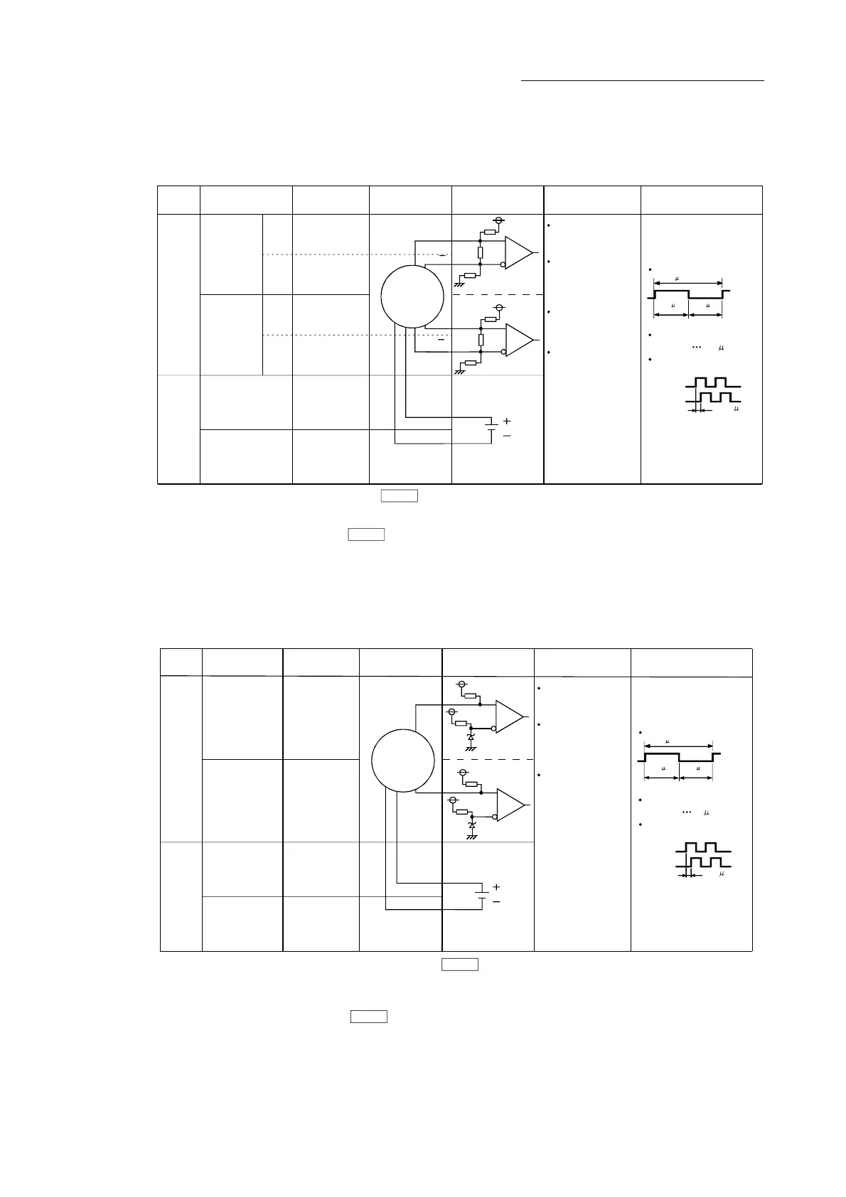
(2) Manual pulse generator/Incremental synchronous encoder input
(a) Interface between manual pulse generator/incremental synchronous
encoder (Differential-output type)
0.5 s
or more
Input or
Output
Signal name Pin No. Wiring example Internal circuit Specification Description
Input
Manual
pulse
generator,
phase A/
PLS
Power
supply
SG
Rated input voltage
5.5VDC or less
HIGH level
2.0 to 5.25VDC
For connection manual
pulse generator/
incremental
synchronous encoder
Phase A
0.25 s or
Phase B
more
(Duty ratio: 50%)
Manual
pulse
generator,
phase B/
SIGN
LOW level
0.8VDC or less
1 s or more
Leading edge, Trailing
edge time 0.25 s or less
Phase difference
(Phases A, B)
1A17
1B17
1A18
1B18
1A15
1B15
1A14
1B14
Manual pulse
generator/
Incremental
synchronous
encoder
5V
SG
A
A
B
B
Power supply
5VDC
A+
HAH
Pulse width
0.5 s
or more
26LS31 or
equivalent
A-
HAL
B+
HBH
B-
HBL
(Note-1),
(Note-2)
(Note-1): Set "0: Differential-output type" in " Manual pulse generator/Incremental synchronous encoder input type
selection" if the manual pulse generator/Incremental synchronous encoder of differential-output type is used.
The default value is "1: Voltage-output/open-collector type".
(Note-2): Set the signal input from in " Manual pulse generator/Incremental synchronous encoder input selection".
(Note-3): The 5VDC power supply from the QD77MS must not be used if a separate power supply is applied to the
manual pulse generator/incremental synchronous encoder.
If a separate power supply is used, use a stabilized power supply of voltage 5VDC.
Anything else may cause a failure.
Pr.24
Pr.89
(1) Positioning address
increases if Phase A
leads Phase B.
(2) Positioning address
decreases if Phase B
leads Phase A.
5V
(Note-3)
(b) Interface between manual pulse generator/Incremental synchronous
encoder (Voltage-output/open-collector type)
A
Manual pulse
generator/
Incremental
synchronous
encoder
5V
SG
B
Power supply
5VDC
2.5 s
or more
Input or
Output
Signal name Pin No. Wiring example Internal circuit Specification Description
Power
supply
SG
Rated input voltage
5.5VDC or less
HIGH level
3 to 5.25VDC/
2mA or less
For connection manual
pulse generator/
incremental
synchronous encoder
Phase A
1.2 s or
Phase B
more
(Duty ratio: 50%)
LOW level
1VDC or less/
5mA or more
5 s or more
Leading edge, Trailing
edge time 1.2 s or less
Phase difference
(Phases A, B)
1B19
1B20
1A15
1B15
1A14
1B14
Pulse width
2.5 s
or more
Manual
pulse
generator,
phase A/PLS
HA
Manual
pulse
generator,
phase B/SIGN
HB
Input
(Note-1),
(Note-2)
(Note-1): Set "1: Voltage-output/open-collector type" in " Manual pulse generator/Incremental synchronous
encoder input type selection" if the manual pulse generator/Incremental synchronous encoder of voltage-
output/open-collector type is used.
The default value is "1: Voltage-output/open-collector type".
(Note-2): Set the signal input from in " Manual pulse generator/Incremental synchronous encoder input selection".
(Note-3): The 5VDC power supply from the QD77MS must not be used if a separate power supply
is applied to the manual pulse generator/Incremental synchronous encoder.
If a separate power supply is used, use a stabilized power supply of voltage 5VDC.
Anything else may cause a failure.
Pr.24
Pr.89
5V
(Note-3)
(1) Positioning address
increases if Phase A
leads Phase B.
(2) Positioning address
decreases if Phase B
leads Phase A.

 Loading...


