7 - 8
Chapter 7 Memory Configuration and Data Process
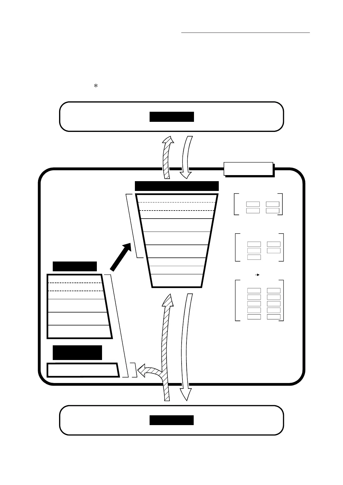
7.2 Data transmission process
The data is transmitted between the QD77MS memories with steps (1) to (10) shown
below.
: The data transmission patterns numbered (1) to (10) on the right page correspond
to the numbers (1) to (10) on the left page.
QD77MS
PLC CPU
Servo amplifier
(2) Valid upon execution of
the TO instruction.
Parameter area (a)
Parameter area (b)
(3) PLC READY signal
[Y0] OFF ON: Valid
Pr.8 Pr.10
Pr.25 Pr.42
Pr.84
Pr.1 Pr.7
Pr.11 Pr.24
Pr.43 Pr.57
Pr.80 Pr.83
Pr.89 Pr.95
to
to
to
to
to
to
to
(1) Power supply ON/
PLC CPU reset : Valid
Parameter area (c)
Pr.96
Pr.800 Pr.807to
Pr.97
,
Parameter area (a)
Parameter area (b)
Positioning data area
(No.1 to
600)
Block start data area
(No.7000 to 7004)
Servo parameter area
Flash ROM
(1) Power supply ON/
PLC CPU reset
Parameter area (c)
Servo parameter area
Internal memory
(nonvolatile)
Buffer memory/Internal memory
Parameter area (a)
Parameter area (b)
Positioning data area
(No.1 to
600)
Block start data area
(No.7000 to 7004)
PLC CPU
memo area
Monitor data area
Control data area
Servo parameter area
(2) TO command
(4) FROM command
(5) Servo amplifier data read
Parameter area (c)

 Loading...


