1 - 19
Chapter 1 Product Outline
1.1.5 Outline design of positioning system
The outline of the positioning system operation and design using the QD77MS is
shown below.
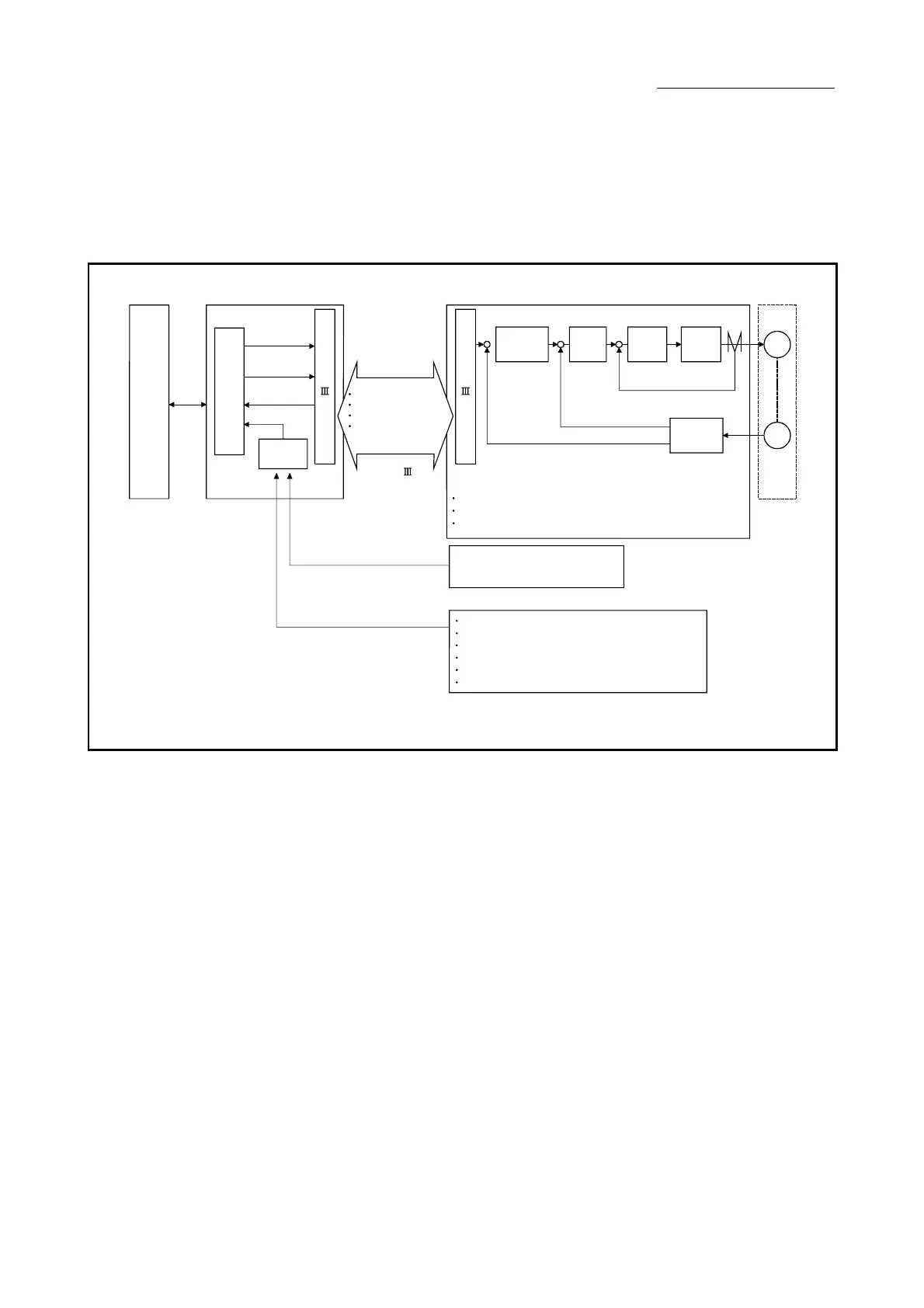
(1) Positioning system using QD77MS
S
S
C
N
E
T
I
/
F
/
H
(
(
External input signal of servo amplifier (Refer to the servo
amplifier Instruction manual.)
FLS (Upper limit signal)
(Note)
RLS (Lower limit signal)
(Note)
DOG (Near-point dog signal)
(Note)
External input signal (Refer to Section 3.4.2)
Manual pulse generator/
Incremental synchronous encoder
A-phese/B-phese
EMI (Forced stop input signal)
FLS (Upper limit signal)
(Note)
RLS (Lower limit signal)
(Note)
DI (External command signal/Switching signal)
STOP (STOP signal)
DOG (Near-point dog signal)
(Note)
SSCNET (/H)
Positioning command
Control command
Monitor data
External input signal
of the servo amplifier
Read,
write
and
etc.
PLC
CPU QD77MS
OS
Monitor data
Interface
Positioning
command
Control
command
(Note): The external input signal of QD77MS, external input signal of servo amplifier,
or external input signal via CPU (buffer memory of QD77MS) can be used in
the parameter settin
.
Refer to Section 5.2.3.
Servo
motorServo amplifier
Interface
M
PLG
Positioning
control
Speed
control
Current
control
Inverter
Current feedback
Speed feedback
Position feedback
+
-
+
-
+
-
S
S
C
N
E
T
I
/
F
/
H
(
(
Fig. 1.1 Outline of the operation of positioning system using QD77MS

 Loading...


