Appendix - 2
Appendices
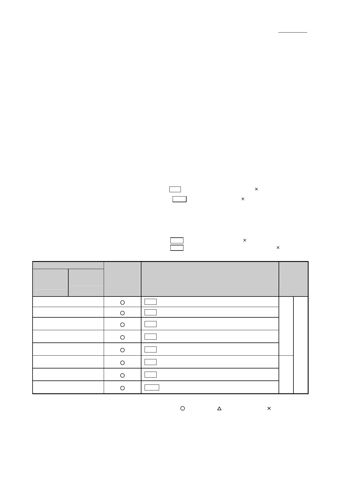
Appendix 1 List of buffer memory addresses
The following shows the relation between the buffer memory addresses and the
various items.
(Note-1): Do not use the buffer memory address that not been described here for a
"Maker setting".
(Note-2): For the list of buffer memory addresses for positioning data, refer to the
"Simple Motion Module Setting Tool Help" of GX Works2.
(Note-3): For the list of buffer memory addresses used in synchronous control, refer to
the "MELSEC-Q/L QD77MS/LD77MH Simple Motion Module User's Manual
(Synchronous Control)".
(Note-4): Guide to buffer memory address
•In the buffer memory address, "n" in "1+150n", etc. indicates a value
corresponding to axis No.
Calculate as follows for the buffer memory address corresponding to each
axis.
(Example) For axis No. 16
1+150n (
Pr.4 Unit magnification (AM))=1+150 15=2251
53+150n (
Pr.35 S-curve ratio)= 53+150 15=2303
•In the buffer memory address, "p" in "4012+5p", etc. indicates a pointer No.
Calculate as follows for the buffer memory address corresponding to each
pointer No.
(Example) For pointer No. 15
4012+5p ( Md.3 Start information)=4012+5 15=4087
4093+4p ( Md.9 Axis in which the error occurred)=4093+4 15=4153
Buffer memory address
QD77MS2
QD77MS4
QD77MS16
Compatibility
of setting value
of QD77MS2/
QD77MS4 and
QD77MS16
Item
Memory
area
0+150n
Pr.1
Unit setting
1+150n
Pr.4
Unit magnification (AM)
2+150n
3+150n
Pr.2
Number of pulses per rotation (AP)
4+150n
5+150n
Pr.3
Movement amount per rotation (AL)
6+150n
7+150n
Pr.7
Bias speed at start
Basic parameters 1
10+150n
11+150n
Pr.8
Speed limit value
12+150n
13+150n
Pr.9
Acceleration time 0
14+150n
15+150n
Pr.10
Deceleration time 0
Basic
parameters 2
Positioning parameters
n: Axis No.-1
: Compatible : Partly compatible : Not compatible

 Loading...


