3 - 28
Chapter 3 Specifications and Functions
3.4.4 Interface internal circuit
The outline diagrams of the internal circuits for the QD77MS external device
connection interface are shown below.
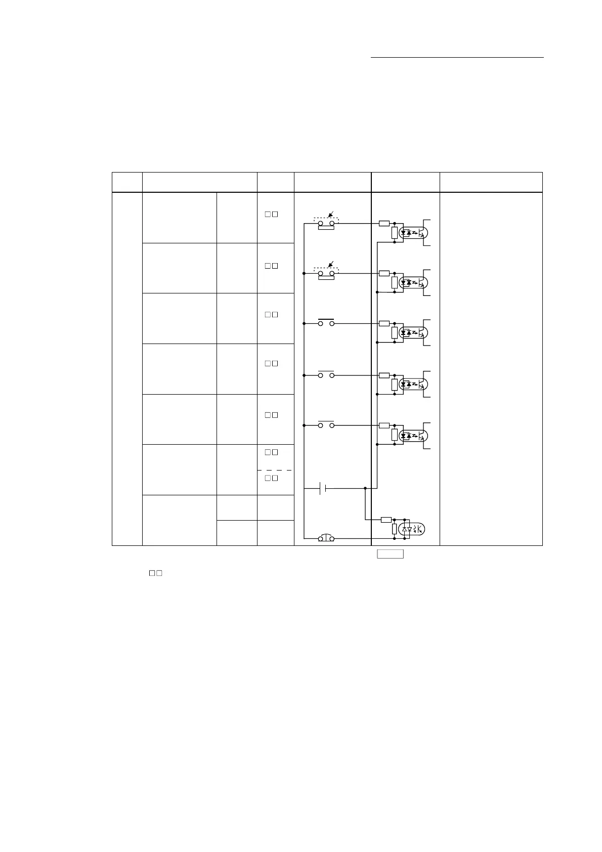
(1) Interface between external input signals/forced stop input signals
Input or
Output
Signal name Pin No. Wiring example Internal circuit Description
Input
1A8
1B8
(Note-1): When using external input signal of servo amplifier, set "1" with " External signal selection". In addition,
refer to Sectopn 13.4.4 for wiring of upper/lower limit signal and Section 8.1.1 for wiring of near-point dog signal.
(Note-2): " " indicates "1A (AX1)", "1B (AX2)", 2A (AX3)", or "2B (AX4)".
(Note-3): As for the 24VDC sign, both "+" and "-" are possible.
Pr.80
Upper-limit signal,
Lower-limit signal,
Near-point dog signal,
Stop signal,
External command signal,
Switching signal,
Forced stop input signal
Upper-limit signal
(Note-1)
FLS
RLS
DOG
STOP
DI
COM
EMI
EMI.COM
Lower-limit signal
(Note-1)
Near-point dog
signal
(Note-1)
Stop signal
External command/
Switching
Common
Forced stop input
signal
24VDC
(Note-3)
Without using
Upper-limit switch
Without using
Lower-limit switch
1
(Note-2)
2
(Note-2)
3
(Note-2)
4
(Note-2)
5
(Note-2)
6
(Note-2)
7
(Note-2)

 Loading...


