10 - 28
Chapter 10 High-Level Positioning Control
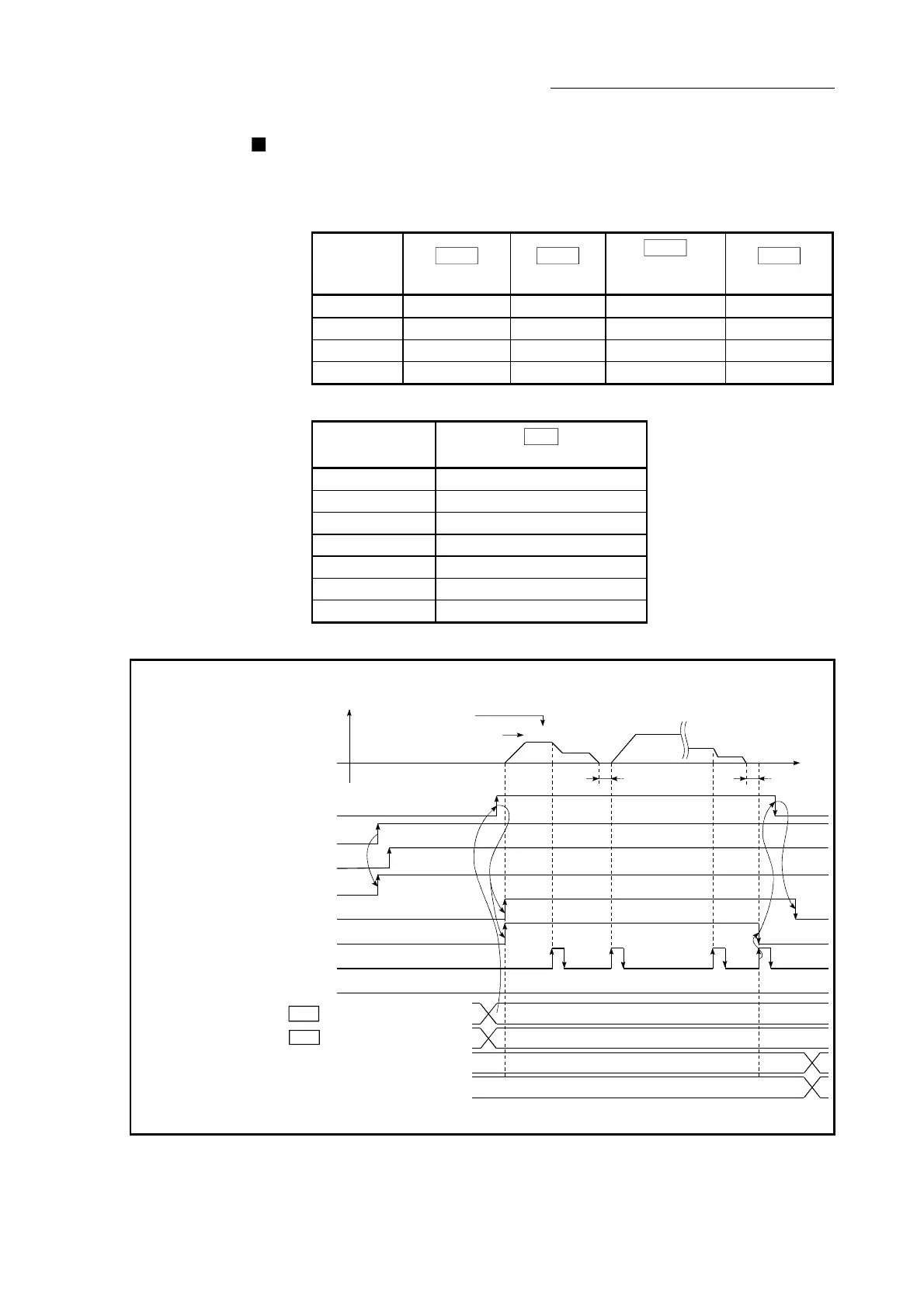
Start time chart
The following chart shows a time chart in which the positioning data No. 1, 2, 10,
11, and 12 of QD77MS4 [axis 1] are continuously executed as an example.
(1) Block start data setting example
Axis 1 block
start data
Da.11
Shape
Da.12
Start data No.
Da.13
Special start
instruction
Da.14
Parameter
1st point 1: Continue 1 0: Block start –
2nd point 0: End 10 0: Block start –
•
•
(2) Positioning data setting example
Axis 1 positioning
data No.
Da.1
Operation pattern
1 11: Continuous path control
2 00: Positioning complete
•
10 11: Continuous path control
11 11: Continuous path control
12 00: Positioning complete
•
(3) Start time chart
[QD77MS4 operation example]
[Y10]
PLC READY signal
QD77 READY signal
[X10]
[XC]
Positioning complete signal
V
t
Error detection signal
Positioning data No.
Dwell time
12(00)
Operation pattern
1(11)
1st point [buffer memory address 26000]
2nd point [buffer memory address 26001]
11(11)
10(11)
2(00)
7000
1
-32767
10
(8001
H)
(000A
H)
Cd.3 Positioning start No.
Cd.4 Positioning starting point No.
Positioning start signal
[X0]
Start complete signal
BUSY signal
[X8]
[X14]
[Y0]
All axis servo ON
[Y1]
Dwell time
(Note): Refer to Section 3.3 for input/output signal or Chapter 5 for buffer memory address of QD77MS16.
Fig. 10.3 Start time chart for high-level positioning control (block start)

 Loading...


