13 - 40
Chapter 13 Control Sub Functions
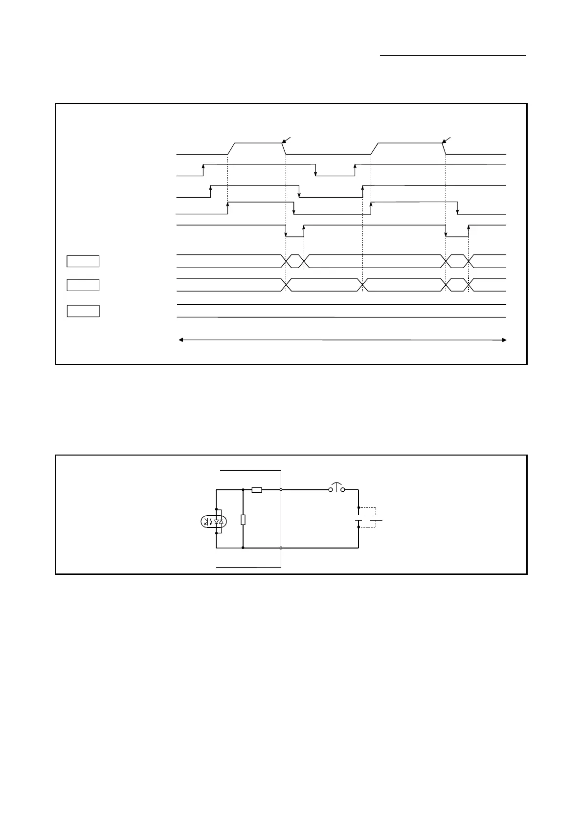
The following drawing shows the operation of the forced stop function.
[QD77MS4 operation example]
Each operation
PLC READY signal[Y0]
ll axis servo ON[Y1]
Positioning start signal[Y10]
Forced stop input
(Input voltage of EMI)
Md.50
Forced stop input
10
Forced stop
causes occurrence
Pr.82
Forced stop valid/
invalid selection
0
Forced stop valid
Md.108
Servo status
Buffer memory
address: 877
(b1: Servo ON)
ON
01
OFF
1
ON ONOFF
Forced stop
causes occurrence
(Note): Refer to Section 3.3 for input/output signal and Chapter 5 for buffer memory address of QD77MS16.
Fig. 13.20 Operation for the forced stop function
[2] Wiring the forced stop
When using the forced stop function, wire the terminals of the QD77MS forced
stop input as shown in the following drawing. Either polarity can be connected to
the forced stop input (EMI, EMI.COM).
QD77MS
EMI
EMI.COM
24VDC
Fig. 13.21 Wiring when using the forced stop

 Loading...


