13 - 51
Chapter 13 Control Sub Functions
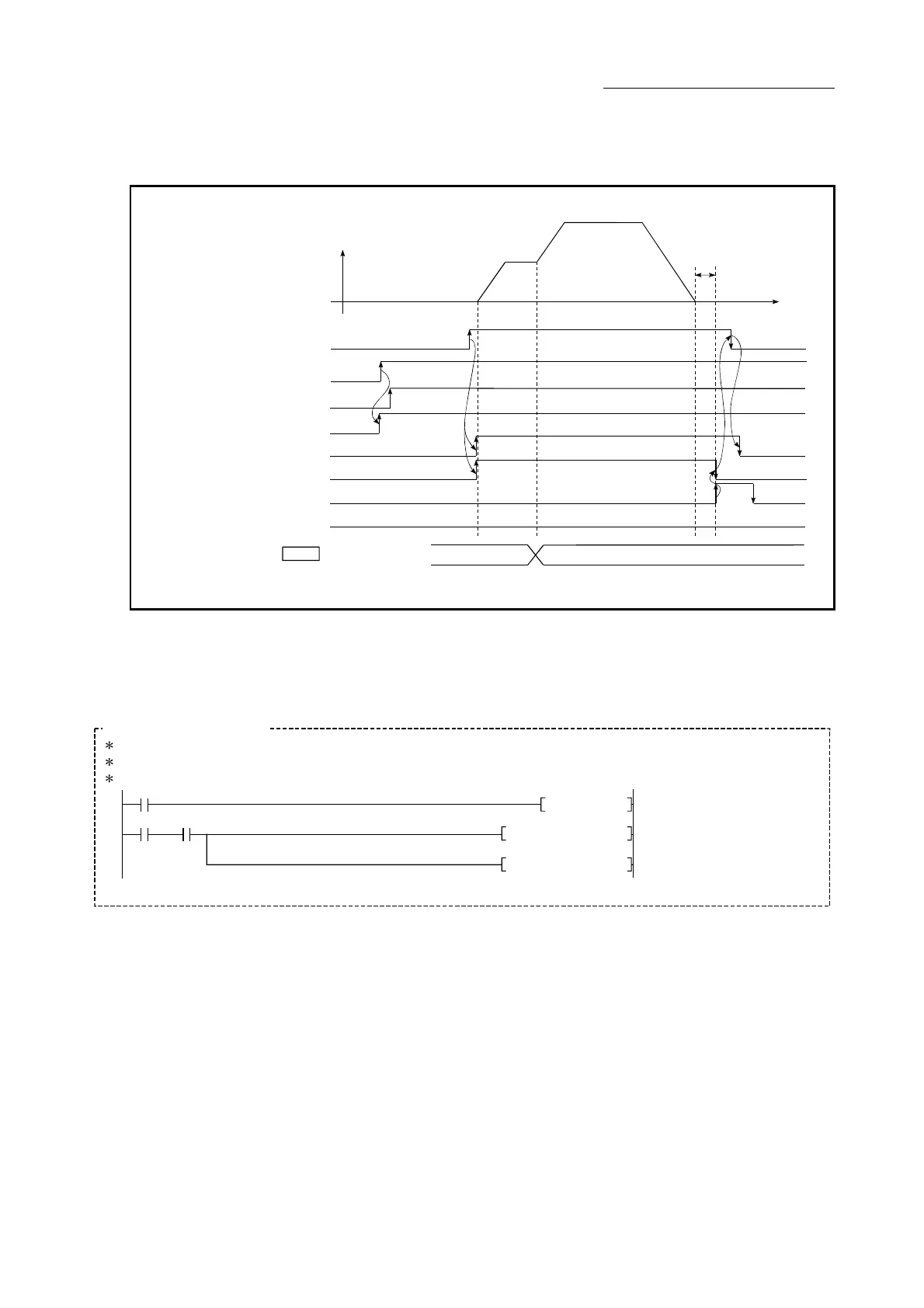
(2) The following shows a time chart for changing the speed using the override
function.
[QD77MS4 operation example]
Cd. 13 Positioning operation
speed override
V
t
Dwell time
200
BUSY signal
Error detection signal
All axis servo ON
Positioning start signal
Positioning complete signal
QD77 READY signal
Start complete signal
[Y10]
[Y1]
[X0]
[X10]
[XC]
[X14]
[X8]
PLC READY signal
[Y0]
(Note): Refer to Section 3.3 for input/output signal of QD77MS16.
Fig.13.29 Time chart for changing the speed using the override function
(3) Add the following sequence program to the control program, and write it to
the PLC CPU.
No.15 Override program
<Pulsate override command>
<Set override value (200%)>
<Write override value>
M13PLS
K200MOV D14
514
521
M13 X0C
D14MOV
UO\
G1513
[QD77MS4 program example]
X33

 Loading...


