14 - 17
Chapter 14 Common Functions
(8) Even if the PLC READY signal [Y0| is turned ON by changing "
Pr.100
Servo series" from "0: Servo series is not set" to other than "0", the setting
does not become valid. (The axis connecting status remains disconnection.)
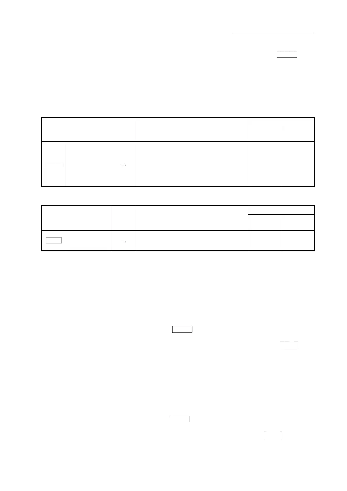
[3] Buffer memory list
The buffer memory used in the amplifier-less operation function is shown below.
(1) System control data
Buffer memory address
Setting item
Setting
value
Setting details
QD77MS2
QD77MS4
QD77MS16
Cd.137
Amplifier-less
operation mode
switching request
Switch operation mode.
ABCDh : Switch from the normal operation
mode to the amplifier-less operation
mode.
0000h : Switch from the amplifier-less
operation mode to the normal
operation mode
1926 5926
(2) System monitor data
Buffer memory address
Monitor item
Monitor
value
Storage details
QD77MS2
QD77MS4
QD77MS16
Md.51
Amplifier-less
operation mode
status
Indicate the current operation mode.
0: Normal operation mode
1: Amplifier-less operation mode
1432 4232
[4] Operation mode switching procedure
(1) Switch from the normal operation mode to the amplifier-less operation
mode
1) Stop all operating axes, and then confirm that the BUSY signal for all
axes turned OFF.
2) Turn OFF the PLC READY signal [Y0].
3) Confirm that the QD77 READY signal [X0] turned OFF.
4) Set "ABCDh" in "
Cd.137
Amplifier-less operation mode switching
request".
5) Confirm that "1: Amplifier-less operation mode" was set in "
Md.51
Amplifier-less operation mode status".
(2) Switch from the amplifier-less operation mode to the normal operation
mode
1) Stop all operating axes, and then confirm that the BUSY signal for all
axes turned OFF.
2) Turn OFF the PLC READY signal [Y0].
3) Confirm that the QD77 READY signal [X0] turned OFF.
4) Set "0000h" in "
Cd.137
Amplifier-less operation mode switching
request".
5) Confirm that "0: Normal operation mode" was set in "
Md.51
Amplifier-
less operation mode status".

 Loading...


