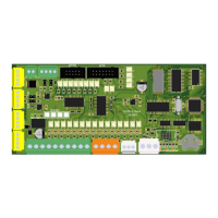
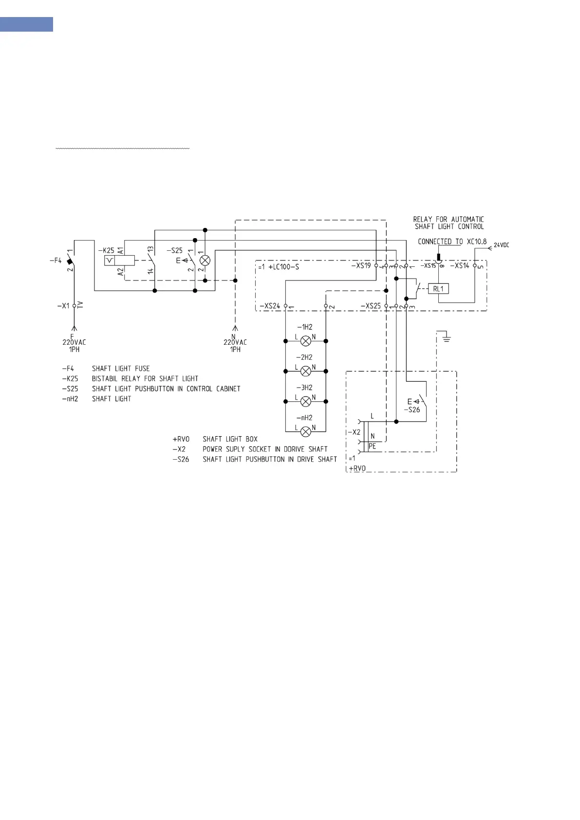
On LC100-S board there are also connectors for connecting the drive shaft light with LED indicator and controling
the status for automatic control of the light (the light is powered automaticly when the inspection mode is on). Shaft
lighting is controled by relay RL1 with output parameter XC10.2.
- XS19 – input connector for shaft light power supply.
- XS25 – connector for shaft light box in the drive shaft pit.
- XS24 – connector for shaft light.
Shaft light connection diagram: