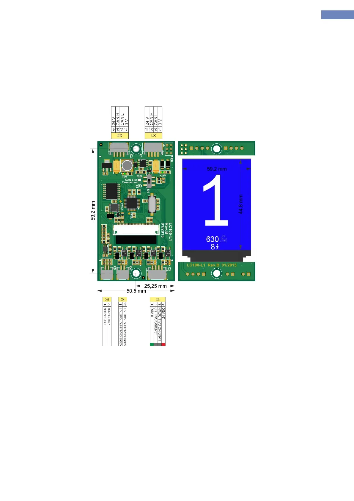
2.21.6 LC100-L1 TFT display
LC100-L1 displays are used as landing displays with connector for connecting the landing calls. Connection to the
displays is made trough XC12 connector which is CAN2 bus.
Each display is addressed for a floor. Addressing is done through the aditional menue for addressing.
What the displays will show can be set trough P-M-L modules TYPE P.
Every landing call unit is addressed, addressing is done trough addressing menue.
To ensure that the landig calls are procesed through landing units parameter A-9 must be set.
Picture 23 - LC100-L1 TFT display