Troubleshooting Charts: Secure Hardware Failure 5-31
5.13 Secure Hardware Failure
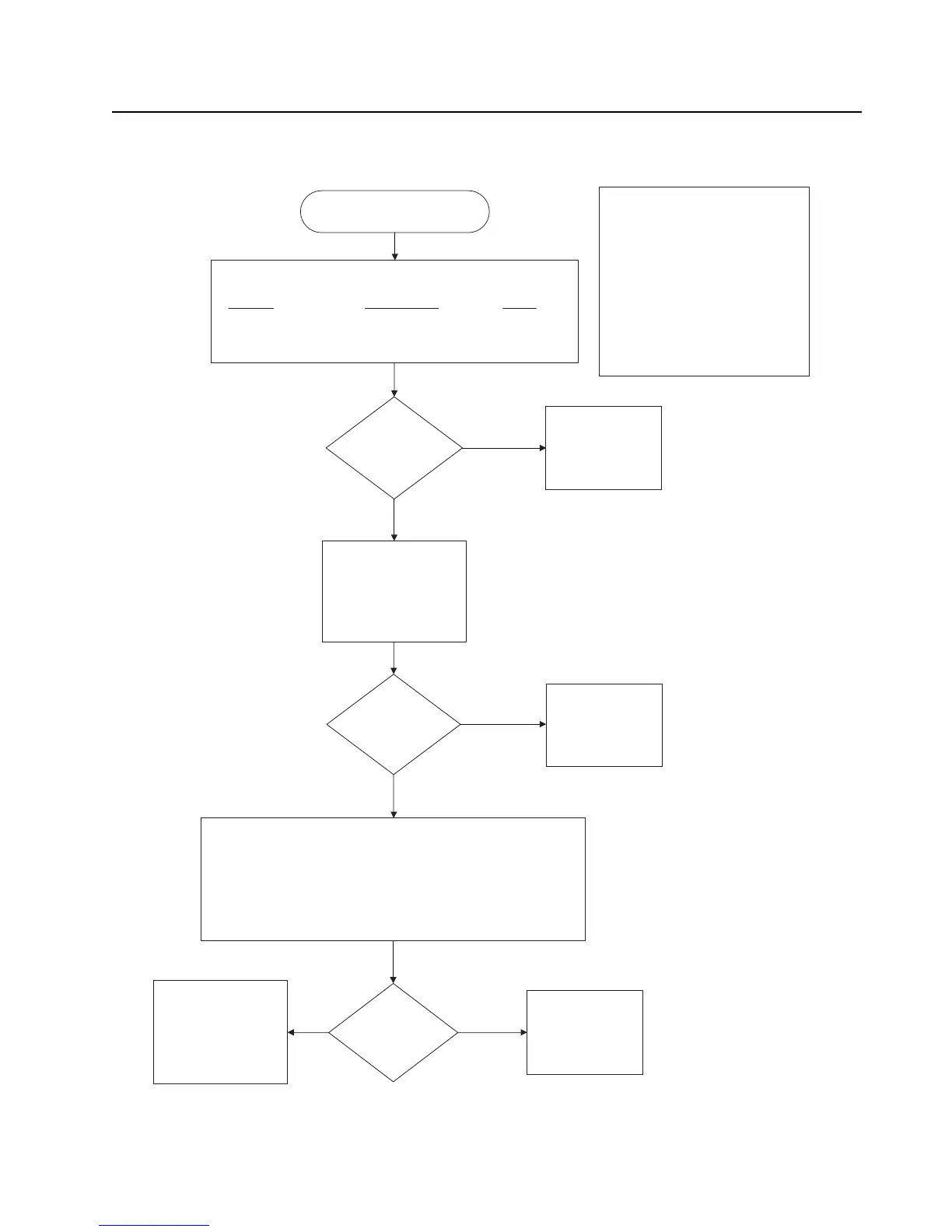
Fail 09/10 or 09/90 Secure
Hardware Failure
Use an ohmmeter to electrically verify the following secure
related signals on the controller board and the Vdd levels:
Signal Probe Point Level
VDD-IOP R5007 1.875 V
VDD_IOM R5008 1.875 V
VDDC R5009 1.875 V
Use a voltmeter to measure voltaVerify electrical activity at
the following signal probre points at power up:
MACE_CODEC_FSYNC R5010
MACE_CODEC_CLK R5003
RED_TX_MACE Test point – F_SSIR_TXMACE
RED_RX_CODEC Test point – F_SSIR_RX_CDC
Replace respective
source IC or
Controller Board
Levels good
good?
Signals good?
Replace
Controller Board
Repair DC
Voltage
Regulators
No
No
Yes
Yes
Synopsis
This failure relates only to secure
equipped radios and indicates a power
up self test failure for the secure
circuitry. More specifically this failure
indicates a failure in communications
between the DSP and the secure
circuitry. The secure circuitry is not
considered to be field repairable so
troubleshooting is limited to verifying a
problem with the secure circuitry and
replacing the controller if required.
Use an oscilloscope to
measure a 4MHz clock
signal at R6113 –
ENC_CLK_4MHz
Signal Present?
No Repair CPLD
circuitry
Yes
Yes

 Loading...


