Theory of Operation: Transceiver Board 3-9
3.1.2 Receiver
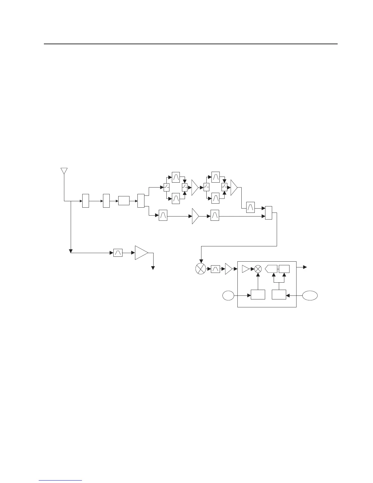
The RF signal is received at the antenna and is routed through the Auxiliary and Multi Switch (SP3T)
ICs. The latter contains a switchable 15 dB attenuator that is enabled at predetermined RF power
thresholds present at the antenna port. The output of the Multi-switch IC is applied to the first SPST
band select switch to select the desired RF band.
• VHF or 7/800 bands (for VHF / 7/800 radios. See Figure 3-9.)
• UHF1 or 7/800 bands (for UHF1 / 7/800 radios. See Figure 3-10.)
• UHF1 or VHF bands (for UHF1 / VHF radios. See Figure 3-11.)
• UHF1 or UHF2 bands (for UHF1 / UHF2 radios. See Figure 3-12.)
• UHF2 or 7/800 bands (for UHF2 / 7/800 radios. See Figure 3-13.)
• UHF2 or VHF bands (for UHF2 / VHF radios. See Figure 3-14.)
Figure 3-9. Receiver Block Diagram (VHF / 7/800)
SW
2:1
700/800
VHF
Abacus III
2nd
LO
18Mhz
CLK
CLK
Dec.
Filter
LO
ADC
ΣΔ
SW
2:1
PER
SP3T
AUX
DPLXR
To
RF/Vocon
Connector
GPS
SSI
* Kit below rev E
does not have
SAW filter
*

 Loading...


