Theory of Operation: Controller 3-59
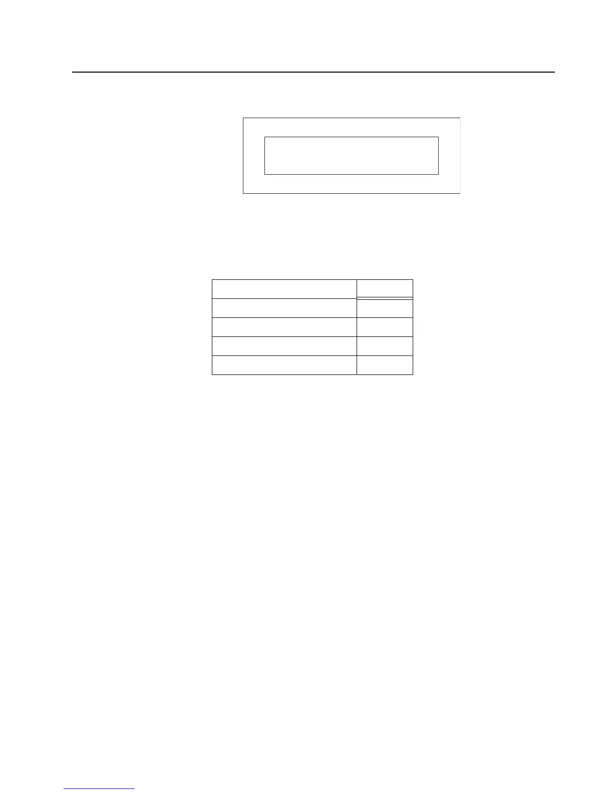
Figure 3-48. Side Button Flex Connector – P2001
3.2.6.6 GCAI
The GCAI (Global Communications Accessory Interface) connector is a 15 pin interface located on
the side of the radio. The connector interfaces the radio with accessories and is used for
programming. When the OMAP (U6501) detects that an accessory has been attached through a
logic low on GPIO0, it will identify the device by reading the GCAI_ONE_WIRE line. Once the device
type is identified, the appropriate signals are multiplexed through MAKO to the GCAI connector for
the particular device. Figure 3-49 is a block diagram of the GCAI interface.
Mounted to the side connector is a printed circuit board that houses ESD protection circuitry and an
auxiliary RF connector. The universal side connector interfaces with the expansion board via the P1
connector of a flex circuit and the J2004 connector of the expansion board. A board-to-board
connection routes universal side connector signals through expansion board connector P2001 to the
controller board. The figures below show the connections and signal assignments from the universal
connector to the controller board.
Table 3-10. Side Button Flex Connector Pin Assignment – P2001
P2001 PIN ASSIGNMENT SIGNAL
24 MON
22 SB2
20 SB1
18 PTT
60 58 ……………………………… 4 2
59 57 …………………………….. 3 1
P2001

 Loading...


