EasyManuals Logo

Motorola APX 7000 Detailed Service Manual

Motorola APX 7000
644 pages
To Next Page IconTo Next Page
To Previous Page IconTo Previous Page
Page #435 background imageLoading...
Page #435 background image
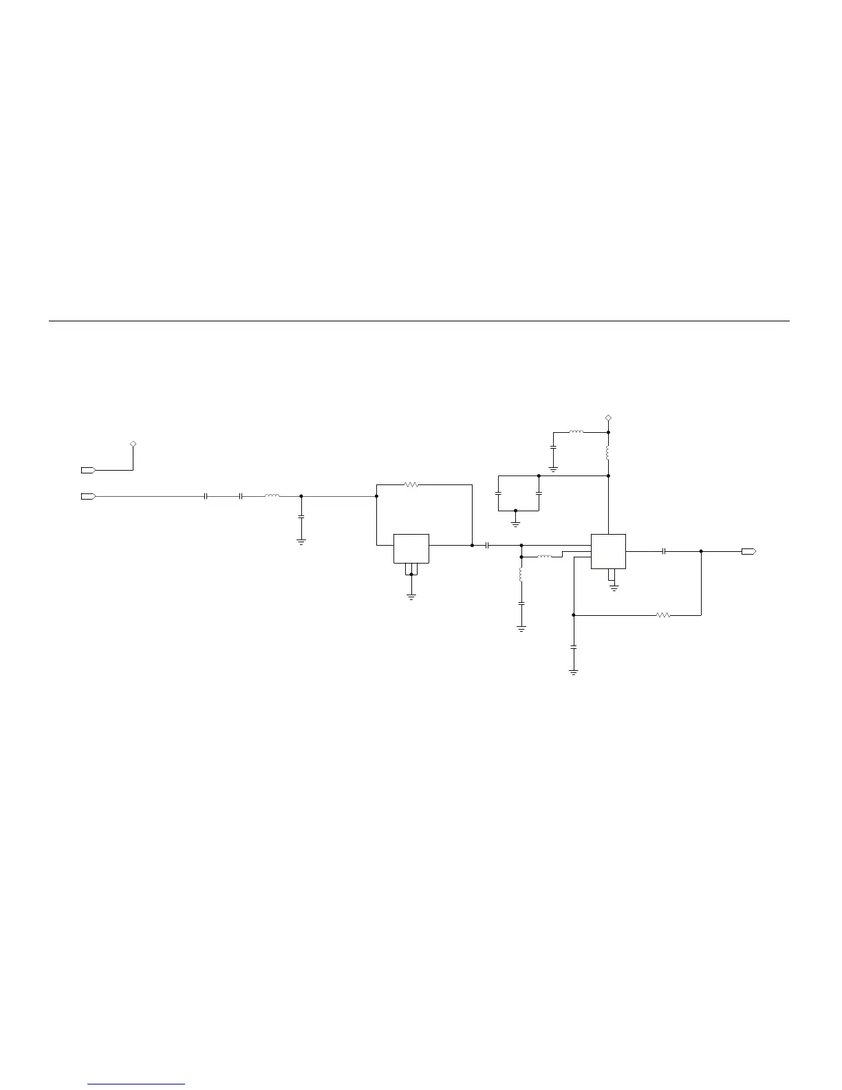
Schematics, Boards Overlays, and Parts Lists: Transceiver (RF) Boards: UHF1/UHF2 8-159
Figure 8-66. MNUE7367A GPS Circuit
DC_LIN_3V
RF_ANT
IN
IN
.5PF
C1309
1.8PF
12PF
L1305
C1301
18NH
C1302
GND1
GND2
OUT
GND3
IN
B9415
FL1301
2
3
5
14
DNP
0
R1304
3.3NH
12PF
100NH
.01UF
C1303
C1306
L1301
L1302
27PF1000PF
C1305
C1304
4.7PF
5.6NH
DC_LIN_3V
100NH
L1303
L1306
C1310
AI
BIAS
PON
VCCGND
DEG
AO
BGA615L7
U1304
1
62
3
7
4
5
TL_RF_GPS_OUT
18PF
C1308
OUT
DC BIAS FOR GPS LNA ADDED TO RF BOARD
(FROM EXPANSION BOARD/GPS IC: GPS_LNA_PON)
12PF
1K
R1307
C1307

Table of Contents

Other manuals for Motorola APX 7000

Questions and Answers:

Question and Answer IconNeed help?

Do you have a question about the Motorola APX 7000 and is the answer not in the manual?

Motorola APX 7000 Specifications

General IconGeneral
Digital TechnologyP25 Phase 1 and Phase 2
Emergency ButtonYes
Frequency Range136-174 MHz (VHF), 380-470 MHz (UHF Range 1), 450-520 MHz (UHF Range 2), 764-870 MHz (700/800 MHz)
DisplayColor LCD
EncryptionAES, DES
Water ResistanceIP67
GPSYes
BluetoothYes
Operating Temperature-30°C to +60°C
Weight391 g (with standard battery)

Related product manuals