Theory of Operation: Transceiver Board 3-3
3.1 Transceiver Board
The transceiver (XCVR) board performs the transmitter and receiver functions necessary to translate
between voice and data from the VOCON board and the modulated radio-frequency (RF) carrier at
the antenna. The transceiver board contains all the radio’s RF circuits for the following major
components:
• Receiver
• Transmitter
• Frequency Generation Unit (FGU)
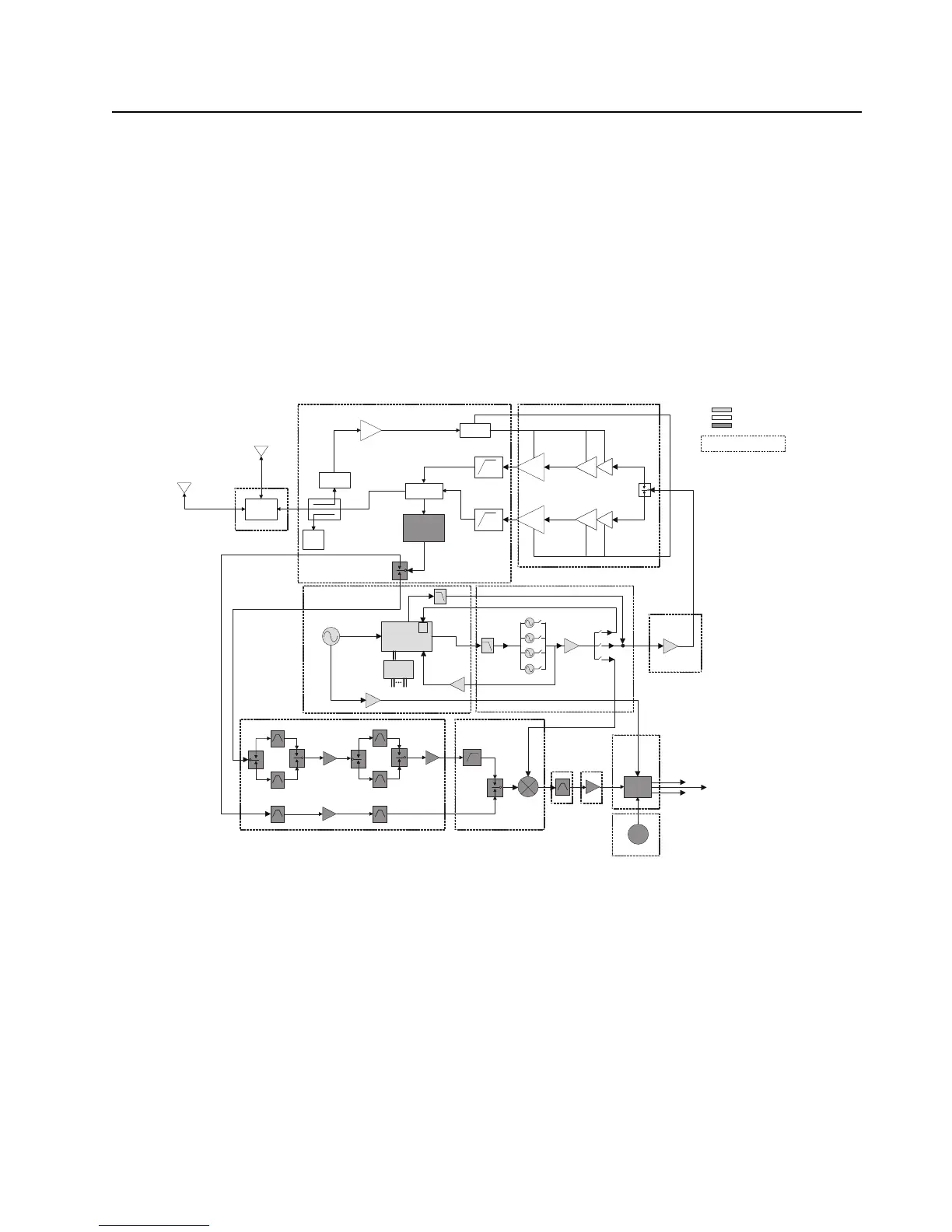
Figure 3-3 illustrates the VHF/7/800 transceiver board block diagram, Figure 3-4, Figure 3-5 and
Figure 3-6 illustrates the UHF1/7/800, UHF1/VHF and UHF1/UHF2 transceiver block diagrams while
Figure 3-7 and Figure 3-8 illustrates the UHF2/7/800 and UHF2/VHF transceiver block diagrams.
Figure 3-3. Transceiver (VHF/ 7/800) Block Diagram (Power and Control Omitted)
FGU
Transmitter
Receiver
SP3T
SP2T
Aux
GPS Di-
Plexer
Abacus
2nd
LO
Digital
RF Atten
Switch
Driver
Amplifier
SP3T Rf Switch
Harmonic
Filters
coupler
Rev
Power
Detector
Log
Amp
FET
VHF
FET
7/800
TRIDENT IC
LOGIC
EXPANDER
LOOP
FILTER
PRESCALAR
BUFFER
RX SSI Data
16.8MHz
BUFFER
PRE
BUFFER
÷
2
TX LO
RX LO
TX
BUFFER
VHF DIVIDE-BY-2
2
ND
HARMONIC FILTER
VHF TX
7/800 TX
VHF/7/800 RX
*
16.8MHz
RX SSI Clock
RX SSI Frame Sync
Indicates Sub-shield
LNA 7/800
LNA VHF
mixer
Main antenna
ux port

 Loading...


