Theory of Operation: Controller 3-29
3.2 Controller
3.2.1 Controller Overview
This section provides a detailed circuit description of the APX 7000/ APX 7000XE controller design.
The controller design consists of the following board and flexes:
Printed Circuit Boards
• VOCON Board
• Expansion Board
• GCAI Connector Board
• Bluetooth Option Board
NOTE: The Bluetooth Option Board, MNUK6000B, is not serviceable to piece part level.
Flexes
• Control Top (Top Display, Buttons, Knobs)
• Front Chassis (Display, Keypad)
• GCAI (Global Core Accessory Interface)
• Side Controls
• Audio Side Microphone / Speaker
• Data Side Microphone
• Data Side Speaker
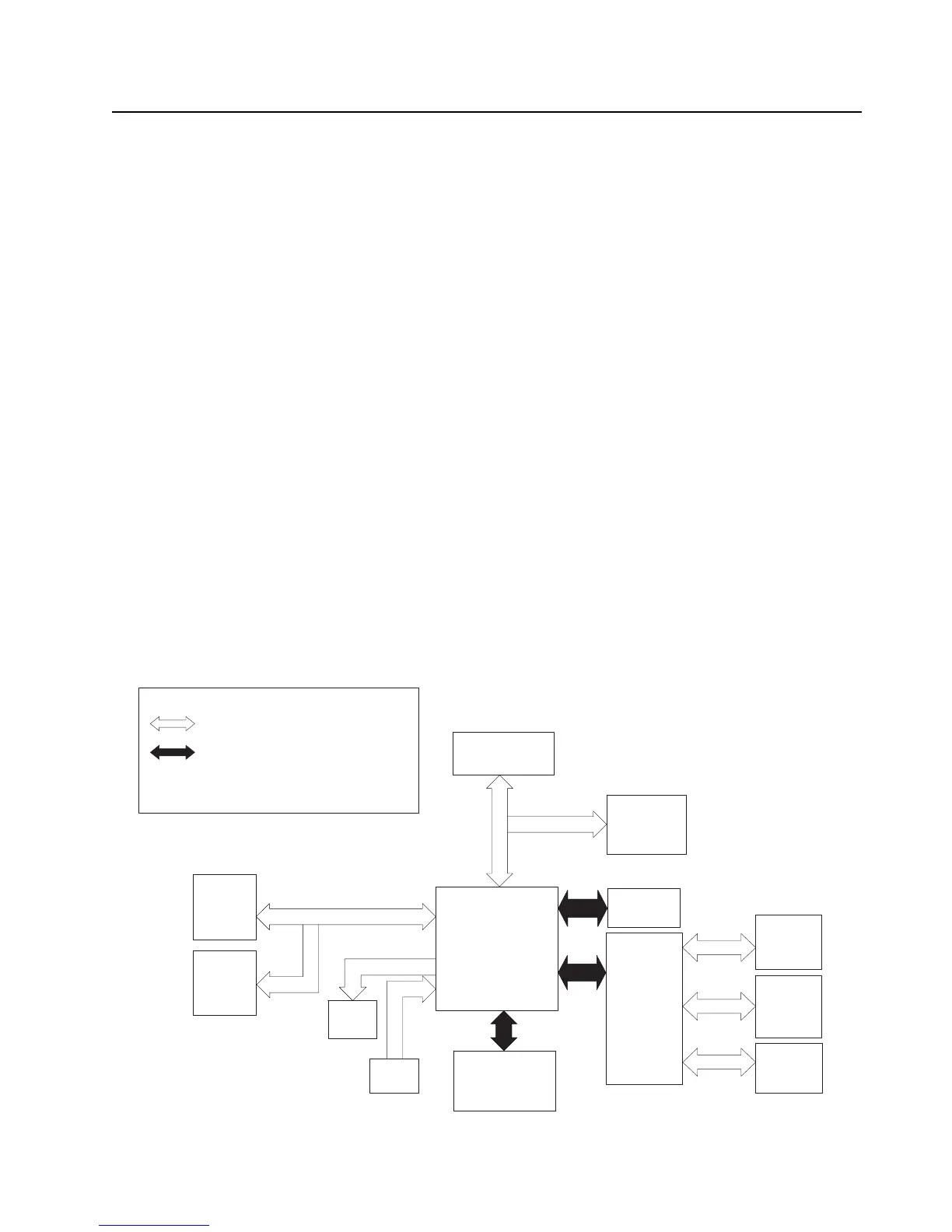
The controller interconnection diagram (Figure 3-22) shows the various physical components of the
design, along with how they are all connected. It also shows the key distinguishes between a flex
connection and a board-to-board connection. A brief description of each of the components is
provided below.
Figure 3-22. Controller Interconnection Diagram
Vocon
Board
Audioside
Speaker
&
Mic
Top Display
Top
Controls
Side
Controls
Conn
GCAI
Spkr
Data
Data
Mic
Expansion
Board
Option
Board
RF Board
Front
Display
*
= Board to Board
Note:
*. Only for Dual-Display version
= Flex
KEY
Keypad
*

 Loading...


