Theory of Operation: Controller 3-51
3.2.6.2 APX 7000/ APX 7000XE LCD Display Modules
3.2.6.2.1 QVGA
The APX 7000/ APX 7000XE radio can have up to 2 displays (QVGA and FSTN) depending upon
the particular feature set and radio model ordered. The main Transflective 2.2" color display is a
QVGA (240 x RGB x 320) active matrix TFT (Thin Film Transistor) LCD. This display is part of the
back chassis subassembly with interconnection passing through the keypad as shown in
Figure 3-43. The QVGA (Part no. 72012006001 and 7275620B01) display consists of 2 interfaces for
communication. It uses a 3-wire SPI bus (LCD_CLK, LCD_DIN, and LCD_CS) to initialize and
program all the internal LCD driver register settings, and an 18-bit RGB interface (I/F) to send the
data/image to the display. Each pixel is 18 bits and sent in parallel across the RGB I/F to produce
262 k color capabilities.
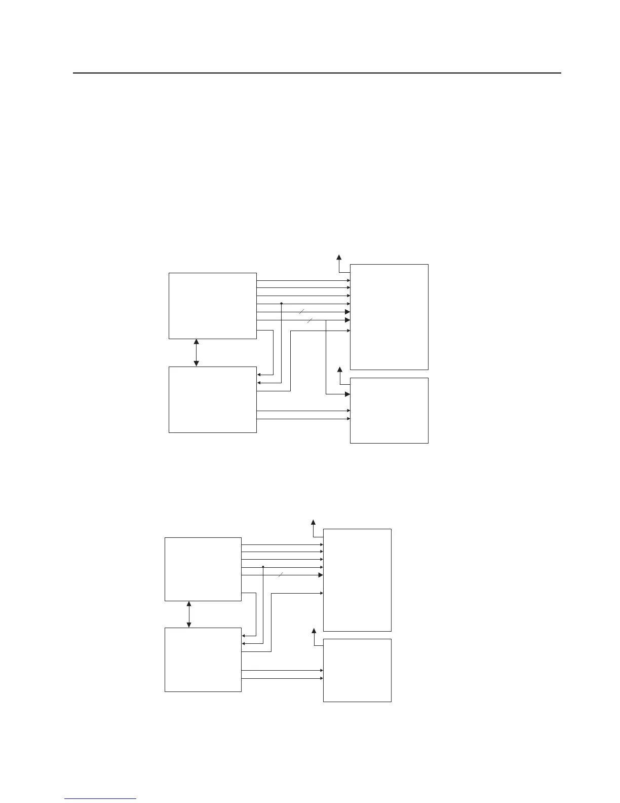
Figure 3-41. Display Circuit Detail Overview Block Diagram (VOCON Board MNCN6200/ MNCN6201)
Note:
*. Only for APX 7000 Dual-Display Version
** FPC = Flexible Printed Circuit
OMAP
Main LCD
*
LCD_AC
P_CLK
HSYNC
VSYNC
P_DATA
SPIF
LCD_OE
DOT_CLK
HSYNC
VSYNC
P_DATA
SPI
18
3
CPLD
LCD_AC
LCD_OE
VSYNC
Pin39
Pin35
Pin B15
Pin B18
Pin J12
Top LCD
LCD_RESET
SPI
LCD_D/C
RESET
D/C
VLED
LED
VLED
LED
RESET
OMAP_RESET
py g
OMAP
Main LCD
*
LCD_AC
P_CLK
HSYNC
VSYNC
P_DATA
LCD_OE
DOT_CLK
HSYNC
VSYNC
P_DATA
18
CPLD
LCD_AC
LCD_OE
VSYNC
Pin55
Pin51
Pin B15
Pin B18
Pin J12
Top LCD
LCD_RESET
LCD_D/C
RESET
D/C
VLED
LED
VLED
LED
RESET
OMAP_RESET
Note:
* Only for Dual-Display Versions (Part no. 7275620B01 & 72012006001)
** FPC = Flexible Printed Circuit

 Loading...


