3-54 Theory of Operation: Controller
3.2.6.3 Intelligent Lighting
The APX 7000/ APX 7000XE radio is equipped with numerous LEDs to provide intelligent lighting
features. The VOCON board contains 2 lighting controller devices, which illuminate all the LEDs
throughout the radio, as shown in Figure 3-44.
VOCON Board MNCN6200
(Dual-Display)/ MNCN6201 (Top Display):
The boost lighting controller, U2203, provides illumination to the main QVGA color display, and
keypad color backlights. The secondary lighting controller, U2201, generates illumination for the top
display backlight, TX/RX indicator lamp, and the keypad white backlights. Both lighting controller
devices are controlled through OMAPs I2C interface (SCL and SDA). Radio models with the top
display only will not have the boost lighting controller and supporting circuitry placed on the VOCON
Board (MNCN6201).
VOCON Board MNCN6202
(Dual-Display)/ MNCN6203 (Top Display) :
The lighting controller IC, U2203, provides illumination to the main QVGA color display, and keypad
color backlights. The secondary lighting controller, U2201, generates illumination for the top display
backlight, TX/RX indicator lamp, and the keypad white backlights. Both lighting controller devices are
controlled through OMAPs I2C interface (SCL and SDA). Radio models with the top display only will
not have the lighting controller IC and supporting circuitry placed on the VOCON Board
(MNCN6203).
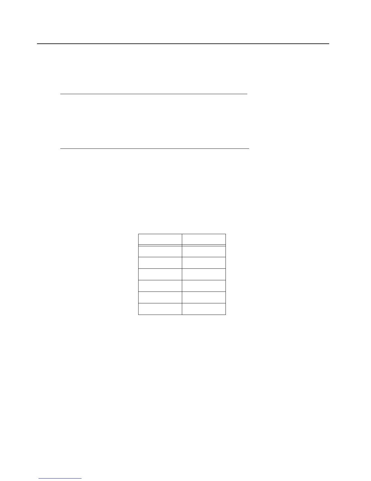
Some of the intelligent lighting color schemes are shown in Table 3-7.
To save on current drain, a switched input voltage supply circuit, net name VDD_LC, was added as
an input to the lighting controllers. The current drain savings occurs while operating in the dim or
standby states of operation for the backlights. The input voltage operates on the 3.6 V external
switcher supply (VCC_SW_3.6) for low current operations, and switches to the external 5 V switcher
(VCC_SW_5) through the P-FET during higher current mode.
Table 3-7. LED Color Codes
Feature Color
Default White
Out of Range Red
Low Battery Red
Emergency Amber
Call Received Green
Call Paged Green

 Loading...


