Theory of Operation: Controller 3-53
For enhanced display readability, the default backlight is set to a dim state while the radio is in
Standby mode; however, the backlight turns to full brightness through a button press, call receive,
emergency call, and other status indicators. See Section 3.2.6.3: "Intelligent Lighting" for the display
backlight operation.
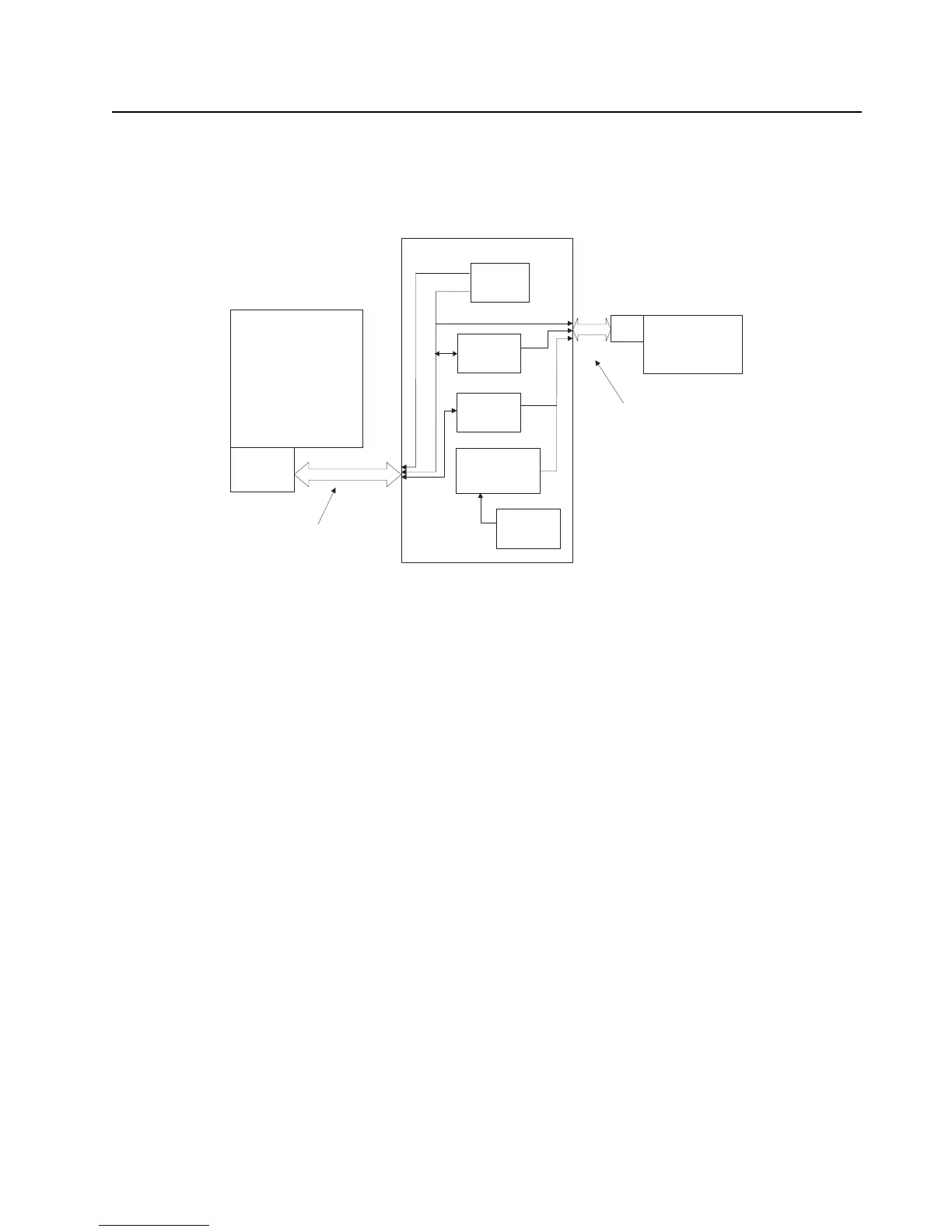
Figure 3-43. Top Level Overview of Lighting Circuit
3.2.6.2.2 FSTN
All APX 7000 and APX 7000XE Radios are equipped with a caller ID (CID) top display. This top
display is a 1.1" (for APX 7000)/ 1.2" (for APX 7000XE), Transflective, FSTN (Film compensated
Super Twisted Nematic) 32 row x 112 column LCD with black pixels on a light background. This
display is a component of the control top sub-assembly with all interconnections passing through
control top FPC, as shown in Figure 3-43. The display is controlled via OMAP's 3 wire SPI
(CID_CLK, CID_DATA, CID_CS) interface to program the display driver IC registers and send data/
image information to the display, as shown in Figure 3-41. The active low chip select line, CID_CS, is
sent from the CPLD GPO pin. The TOP_DIS_D_C line indicates whether the data being sent across
the SPI bus is register/command settings or if it's data/image information. The display driver contains
internal GRAM, which stores the current display content information, and the data/image information
is only sent when the display content needs to be updated.
Prior to sending any information to the LCD driver, the proper power-up sequence must be
instantiated. First, the VCC_SW_1.875 and VCC_2.775D voltage supplies must be stable for at least
1 ms. Next, the active low reset line, CID_RST, to the LCD driver must see a low pulse of 10 usec or
longer prior to communicating to the LCD driver. Then, the register setting information will be sent to
the display driver, followed by the image/data information.
The top LCD contains various LEDs for multiple backlight color combinations depending upon the
mode of operation. The programmable default backlight setting is off in standby mode, but will
illuminate to max brightness during a button push, call receive, receive mode, low battery, out of
range, emergency, etc. The details of the top display backlight settings are listed in Section 3.2.6.3:
"Intelligent Lighting". The top display contains 2 parallel side firing white LEDs and 2 parallel Red-
Green side firing bi-color LEDs.
Main
Color
QVGA
LCD
Module
Vocon Bd
LCD FPC
OMAP
Voltage
Regulators
LCD I/F or SoSSI
TOP LCD
Module
CPLD
KEYPAD/LCD FPC
TOP LCD/CONTROLS FPC
Temp
Sensor
**SPI or SoSSI
LED
Control
I/O
LCD
FPC
*FPC = Flexible Printed Circuit
**SPI = For 7275620B01 & 72012006001 display only

 Loading...


