4.4 Connecting to the Part handler (Handler Interface)
4-21 ZM2371/ZM2372
Checking the operation of handler interface
You can check the operation through outputting the given signal into handler interface or
monitoring the input signal.
Handler interface check menu is as follows:
Handler Check TRIGt RCLsss VLDv LOCKk Input signal monitor
0)OFF 1)DOWN 2)UP 3)EOM BINnn Output options
Signal name which is in dummy output
Perform the EXIT
operation to return to the measurement screen.
Input signal monitor
Numeric values appear while the status of Input signal line is being regarded as the
negative logic input.
0: high level, 1: low level
(It is regarded as negative logic regardless of the setting
of trigger polarity)
0..127: next 7-bit is converted into decimal 3-digit before
displaying
From high order, Pin 29, Pin 4, /RCL4 (MSB), /RCL0
(LSB)
0: High level, 1: Low level
0: High level, 1: Low level
Dummy output signal
Select the each option with the numeric key, the following operation starts:
The signal name (abbreviation) being output appears on the lower right of display.
0)OFF Allows all outputs to turn off (high level)
When handler interface checking menu appears, this status comes out.
1)DOWN Allows output signal to decrease by one smaller in Bin number (see below)
2)UP Allows output signal to increase by one larger in Bin number (see below)
Example of UP operation (DOWN operation allows reversed movement)
(OFF) → /BIN1 → /BIN2 →・・・/BIN14 → /OUT OF BINS →
/S-NG → /INDEX → /EOM → /ERR → (OFF)
Only one of output signals is ON (low level), but others are OFF (high level).
However, all output signals are OFF at (OFF) position.
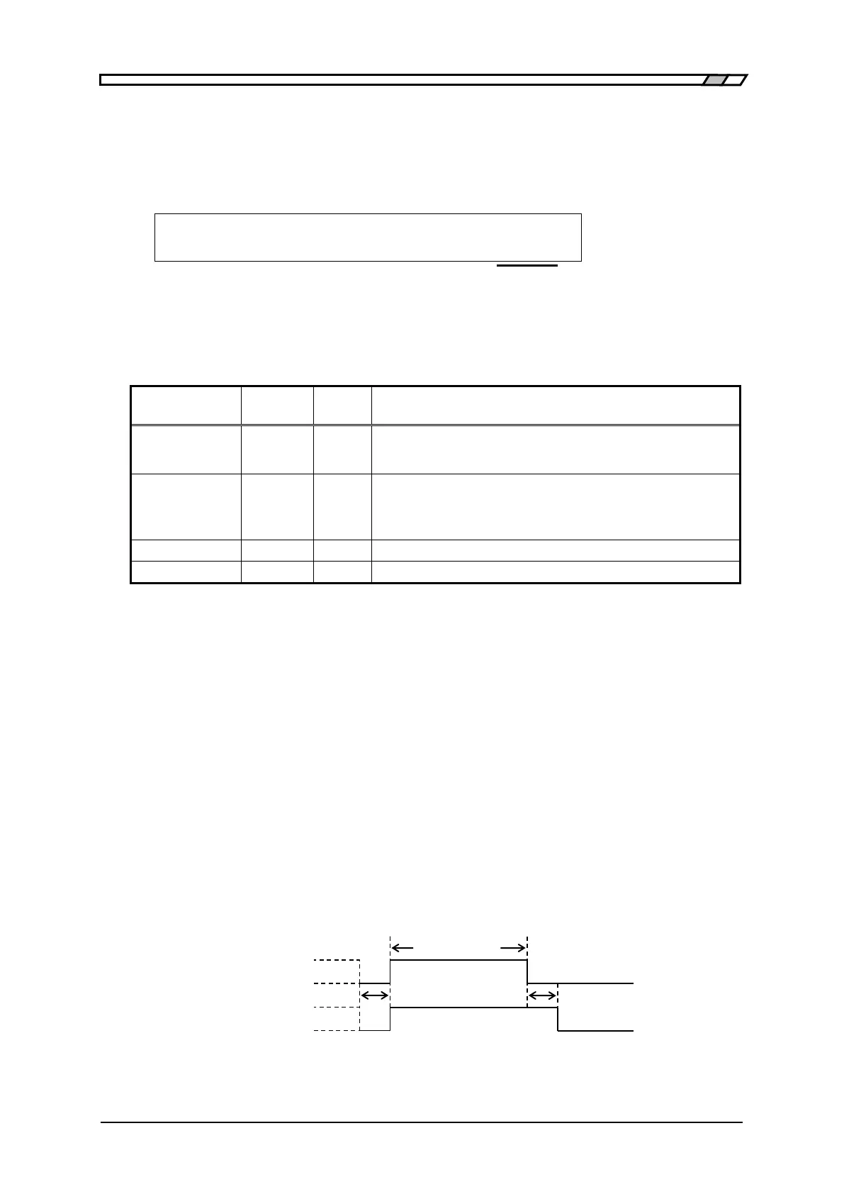
3)EOM /INDEX and /EOM are operated as is the case with the measurement when
trigger is applied but it may not affect on other signals. The change of
signals with the times is fixed as below.
Approx 10ms
/INDEX
/EOM
Approx 1ms Approx 1ms
Figure 4–5 Dummy output timing
 Loading...
