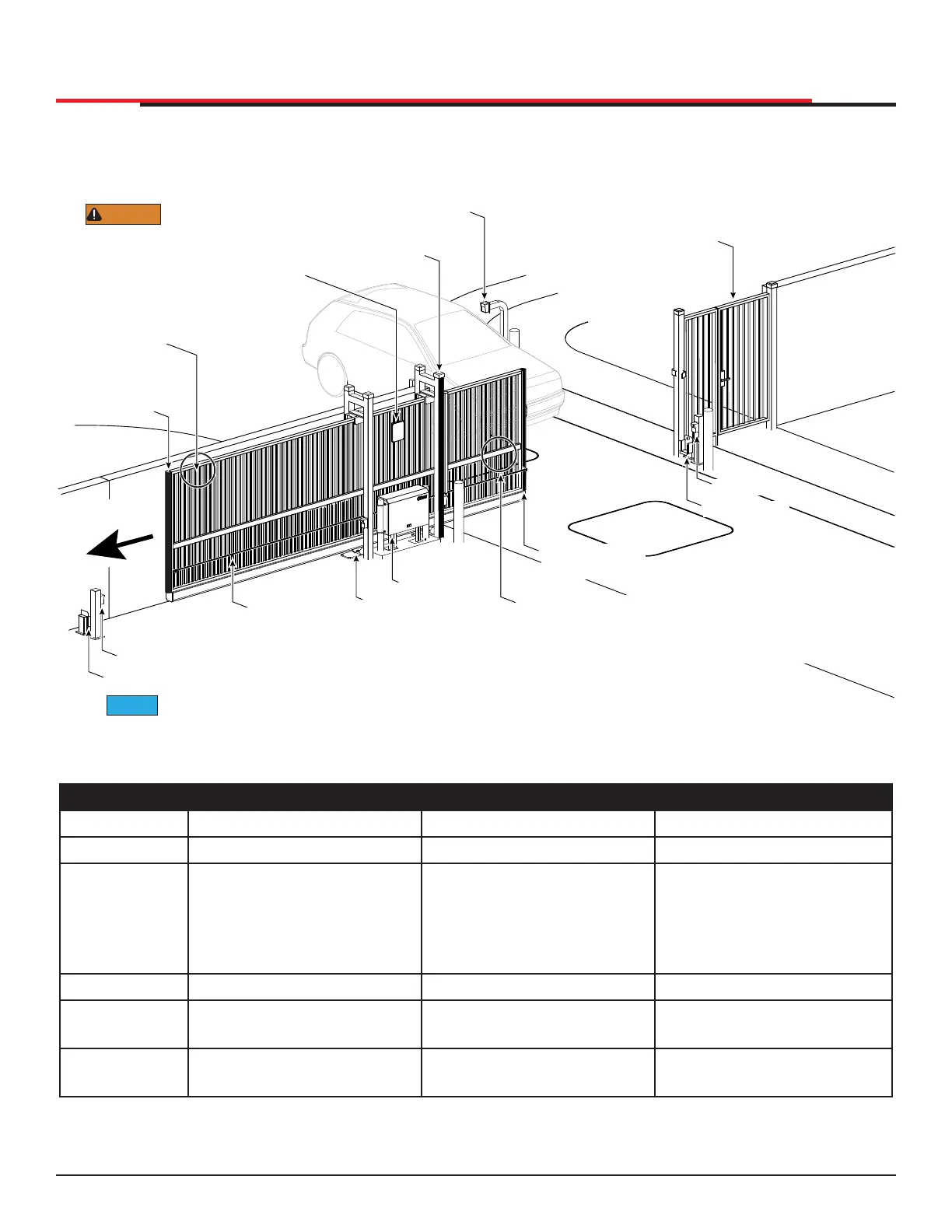
SITE OVERVIEW & PLANNING
Figure 2. Site Overview and Planning
Table 1. SlideSmart Specifications
Operator SlideSmartHD 15F SlideSmartHD 25 SlideSmartHD 30
Duty Cycle Continuous Continuous Continuous
Power, 1Ø
Switch Selectable
115 volts, 3 amps, 50/60
Hertz
208-230 volts, 1.5 amps,
50/60 Hertz
Switch Selectable
115 volts, 3 amps, 50/60
Hertz
208-230 volts, 1.5 amps,
50/60 Hertz
Switch Selectable
115 volts, 3 amps, 50/60
Hertz
208-230 volts, 1.5 amps,
50/60 Hertz
Motor 1 hp ½ hp 1 hp
Gate Speed
1.75, 2.0, 2.25 fps
(53, 61, 68.5 cm/s)
0.75, 1, or 1.25 ft/s
(23, 30 or 38 cm/s)
0.75, 1, or 1.25 ft/s
(23, 30 or 38 cm/s)
Gate Weight
Maximum 1,500 lbs
(680.3 kg)
Maximum 2,500 lbs
(1,134 kg)
Maximum 3000 lbs
(1,361 kg)
Target magnet
on chain
Physical stop - weld stops at both ends of V track
Photo eye (entrapment protection shown in five locations)
SlideSmartHD
Maximum 2¼" (57mm)
width between
vertical bars
To comply with ASTM F2200, a screened wire
mesh extends to the top of the gate or to a mimimum
height of 6 ft. (183cm) if a 2¼" (57mm) or larger gap
exists between the vertical bars.
Edge sensor on
trailing edge
Attach WARNING Signs
Be sure to place the
WARNING signs on both
sides of the gate. For your records, take a
photograph of the completed installation site.
WARNING
Gate Rollers
Edge sensor on
leading edge
Public Side
Secure Side
Key or Card reader
Mount access control
devices at least 6ft
(183cm) beyond the gate.
Pedestrian gate.
Make sure a separate walk-
through entrance is available
and its pedestrian path is
clearly designated.
Physical stop
Photo Eye
Le� Hand Gate
opening
External Entrapment Sensors shown are example mounting locations. Each site will be different depending upon entrapment zone areas.
NOTICE
Edge sensor
INSTALLATION
SlideSmart HD Programming and Operations
1515
MX4435 Rev.G ©2022