SMART DC CONTROLLER
INSTALLING STANDARD 11-PIN BOX TYPE
VEHICLE DETECTORS
If standard 11-pin box type vehicle detectors are
to be used, perform the following procedure.
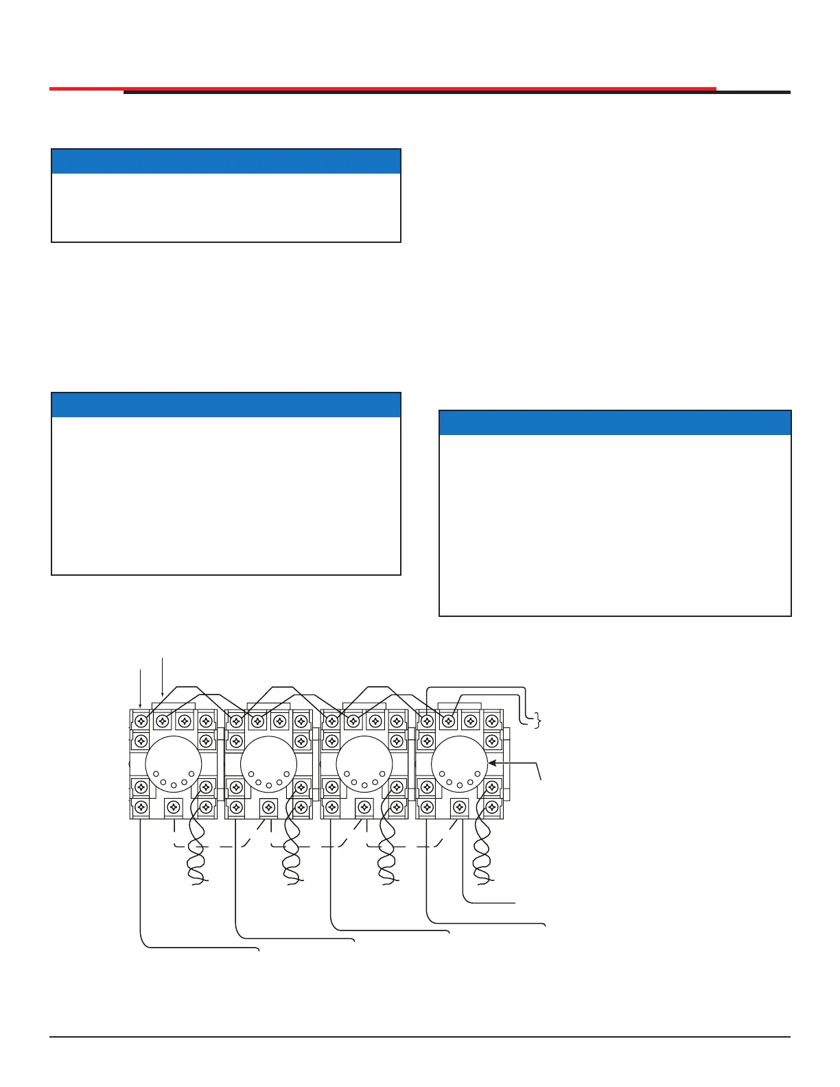
1. If there is sufcient space, install the sockets
in the control box; if not, then install them in
a separate external housing. Figure 53 is for
general reference only.
NOTICE
If photo eyes are used to monitor vehicle trafc
instead of loop detectors, connect the photos
eyes using the same steps described below.
NOTICE
Carefully consider your peripheral connections.
Any peripheral device required for safe gate
operation should be attached 24VDC in case
of an AC power outage. Additionally, box
detectors with relays require ve times more
power than Hy5B detectors. UPS battery life
will be extended if you use Hy5B detectors
instead.
2. Connect 24 Volt power to the detector.
Connect Pin No. 1 to a 24VDC terminal and
Pin No. 2 to Common.
3. Connect output Pin No. 6 to the Common
Bus and output Pin No. 5 to one of the four
detector terminal inputs (depending upon the
detector function required) on the Smart DC
Controller.
4. If multiple detectors are used, route the power
wires and common wire from socket to socket
(daisychaining) rather than individually running
each wire to the same location. See Figure
53. The only wires that are separate are the
output wire to the Smart DC Controller and
the detector loop input wires.
NOTICE
Always keep the detector loop wires well
twisted at all places beyond the area of the
loop. The lead in portion should be twisted
to the detector to help mitigate problems
associated with electrical noise getting into
the loop wires. The wires should then be
encapsulated in the saw cut with a exible loop
sealant. Refer to "Installing Vehicle Detectors
and Loops" on page 83
Figure 53. Standard 11-Pin Box Type Vehicle Detector
Inside
Obstrucon
Loop Detector
Outside
Obstrucon
Loop Detector
Free Exit
Loop Detector
Center
Loop Detector
PIN 1
PIN 2
Common
IN OBS LOOP terminal
OUT OBS LOOP terminal
CENTER LOOP terminal
LOOP
LOOP LOOP
LOOP
24VAC or 24VDC
Connect detector to match
its voltage rating
The center loop serves no
gate function but the detector
can be used as an arming loop
when used in conjunction
with User
Relay 22.
SlideSmart HD Programming and Operations
7171
MX4435 Rev.G ©2022