PRIMARY AND SECONDARY WIRING
CONNECTIONS
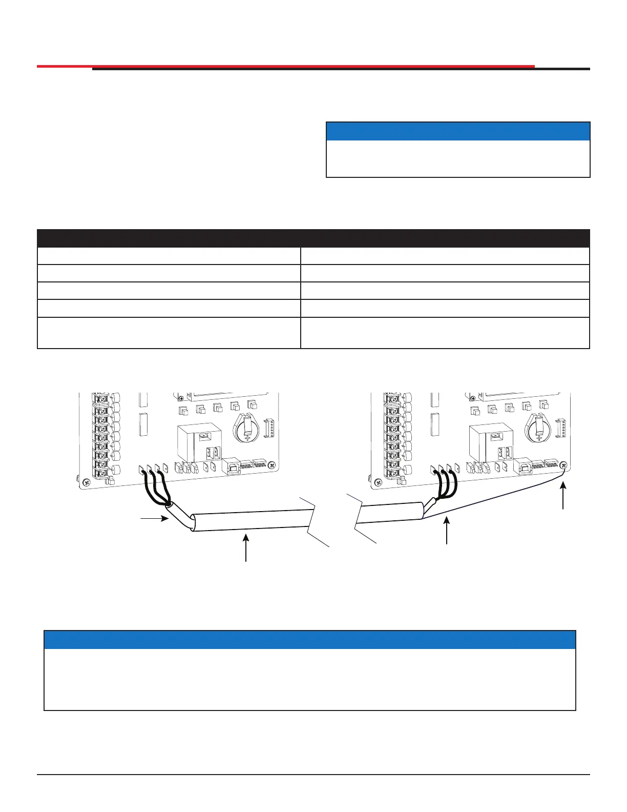
1. As shown in Figure 57, connect a two-pair
twisted, shielded communications cable to
the DUAL GATE inputs in each unit. The inputs
are located near the base of the Smart DC
Controller. Be sure to connect the wires in pairs
to the same terminal ports (A-A, B-B, and COM
to COM) on both units. See Table 15.
BI
-
PARTING GATE SYSTEMS
2. Attach a ring terminal to the shield wire
and connect it to the Smart DC Controller’s
convenient ground screw. Refer to Figure 57.
NOTICE
Connect the ground shield wire to only one
operator, not both.
Table 15. Primary-Secondary Wiring
Primary Secondary
A A
COM COM
B B
* Only ground to one unit. Do NOT attach the
shield wire to both units.
Shield wire to Ground*
Figure 57. Primary-Secondary Pair Wiring Connections
EXIT
LOOP
BLOCK
EXIT
IN OBS
LOOP
OUT OBS
LOOP
CENTER
LOOP
SENSOR 1
SENSOR
COM
+ 24 V
EMERG
OPEN
SHOW
LEDs
A
U
SE
R
2
C
O
M
N
O
D
C
USER 1
EXIT
LOOP
BLOCK
EXIT
IN OBS
LOOP
OUT OBS
LOOP
CENTER
LOOP
SENSOR
1
SENSOR
COM
+ 24 V
EMERG
OPEN
SHOW
LEDs
A
U
SE
R
2
C
O
M
N
O
D
C
USER 1
COM
DUAL GATE
RADIO OPTIONS
A
B
COM
OPEN
+24V
S1
COM
DUAL GATE
RADIO OPTIONS
A
B
COM
OPEN
+24V
S1
Shielded cable
(2-wire twisted pair)
Conduit (in the ground)
Shield wire
Note: Do not
connect the
ground shield
wire at both ends.
Ground
Primary
Secondary
NOTICE
Use a 2-pair, twisted, shielded cable with one pair of wires used to connect A-A and B-B terminals
between the two boards. The other pair will connect the Common terminals. The shield should
then be grounded on one end to one of the operators.
SlideSmart HD Programming and Operations
7979
MX4435 Rev.G ©2022