SMART DC CONTROLLER
OVERVIEW OF THE SMART DC CONTROLLER
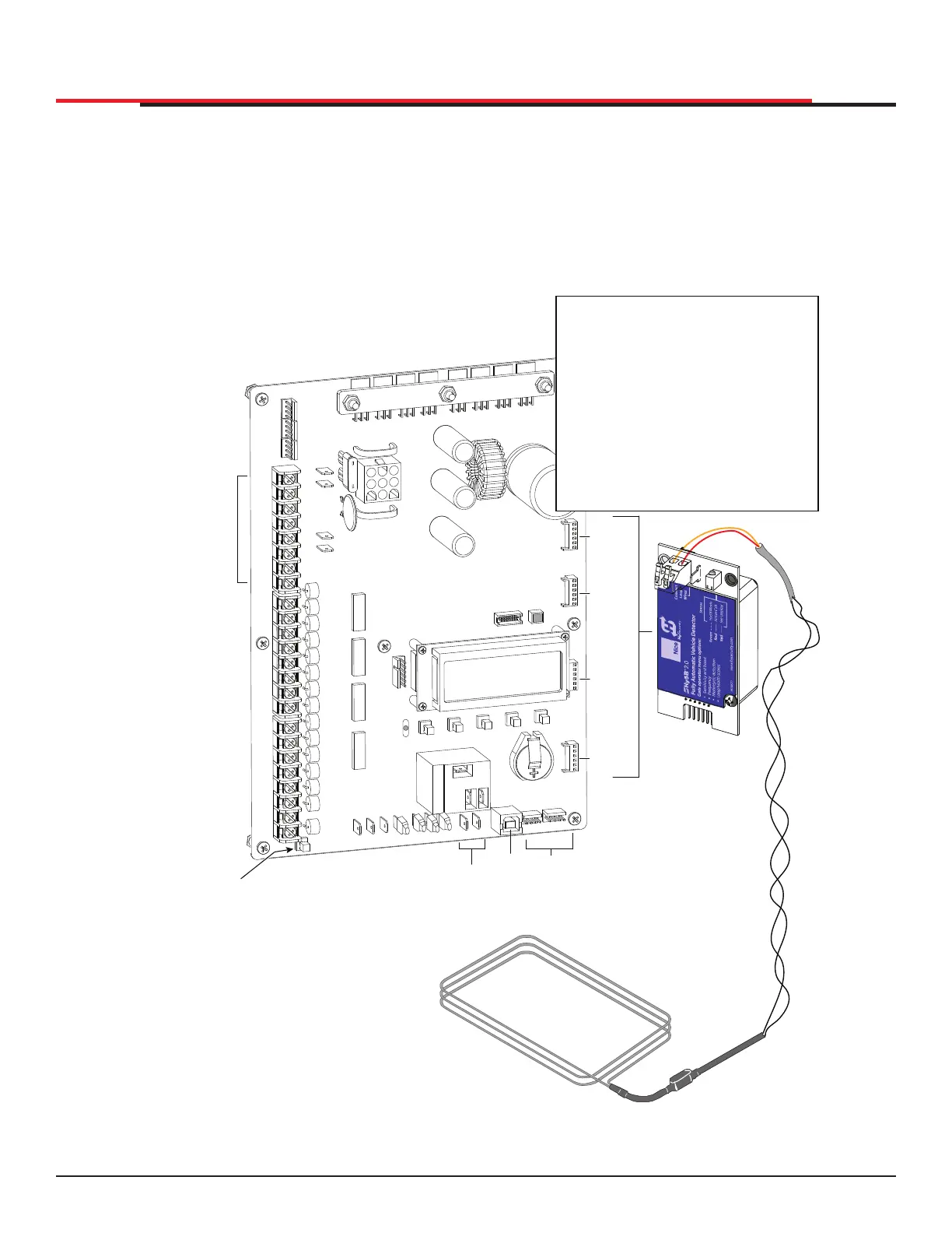
The Smart DC Controller uses LED’s to indicate active inputs when AC power is present. For operators
that use only DC power, you can push a button to show the active inputs. This button is at the bottom
left corner near the EMERG OPEN input.
On a new operator no active inputs should appear until external accessories and wiring are attached. If
any inputs are active before connecting external wiring, refer to "Smart DC Controller Troubleshooting"
on page 92.
Figure 51. Smart DC Controller
COM
COM
COM
COM
COM
COM
COM
COM
STOP
OPEN
RADIO
CLOSE
OPEN
OPEN
PARTIAL
SENSOR
2
SENSOR
3
SENSOR
1
EXIT
LOOP
BLOCK
EXIT
IN OBS
LOOP
OUT OBS
LOOP
CENTER
LOOP
SENSOR
COM
+ 24 V
EMERG
OPEN
SHOW
LEDs
COMMON
TERMINALS
HY-5B
FREE EXIT
HY-5B
INSIDE LOOP
HY-5B
OUTSIDE
LOOP
HY-5B
CENTER
LOOP
RS-485
COMMUNICATION
USB
PORT
USER RELAY 1
Electro-mechanical
USER
RELAY
2
Solid state
24VDC
24VDC
12VDC
12VDC
Press button to
light active inputs
COM
B
A
DUAL GATE
COM
OPEN
+24V
RADIO
OPTIONS
S1
COM
NO
USER2
DC
Amp Draw on Power Supplies
Two power supplies are available:
24VDC and 12VDC
A maximum draw of 1A is available
for each power supply.
NOTE: The 24VDC power supply has
four terminals that can be used in any
combination to draw the available 1A
maximum.
For example:
Amp Draw & Accessories connected to 24VDC
0.50A = Four photo eyes (for entrapment protection)
0.25A = Keypad with light
0.015A = Three HY-5B detectors
0.76A
SlideSmart HD Programming and Operations
6565
MX4435 Rev.G ©2022