INSTALLATION
PAD CONDITION
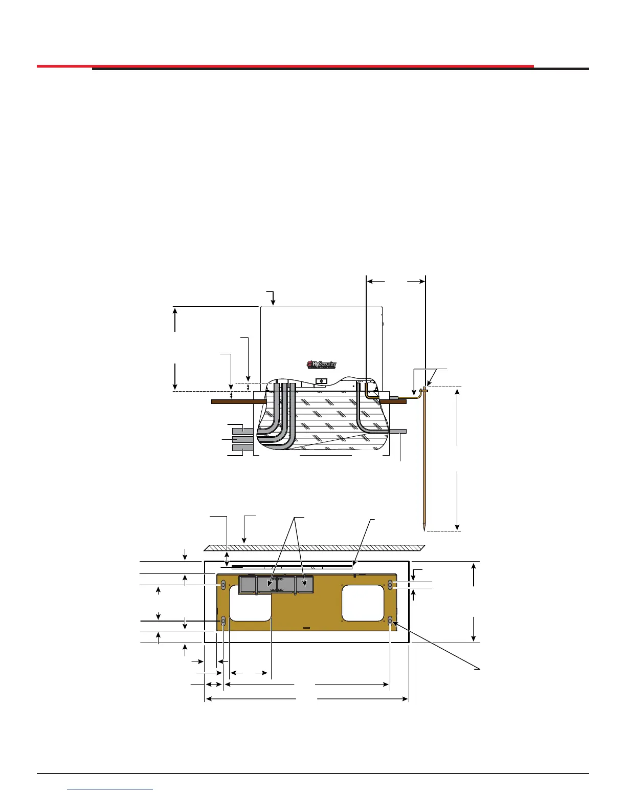
1. Follow the local building codes to identify the
frost line and determine the required depth of
the concrete pad. HySecurity recommends a
minimum 16-inch depth with a minimum 2-inch
extension. Refer to Figure 3.
2. Before pouring the pad, consider conduit
placement so it ts within the connes of the
7 x 6-inch cutout in the SlideSmart base as
shown in Figure 3. Run separate conduits for:
z high voltage wiring (115/230V supply power)
including equipment ground
z low voltage wiring (12V and 24V accessory
power)
• vehicle loop control wiring
• primary/secondary connections
z earth ground (NEC/NFPA)
3. Extend conduit height 2-inches (5cm) above
the pad (4-inches (9cm) above ground level).
Make sure the concrete forms are square with
the gate and the pad is level. The operator
footprint, with covers, is approximately 30 x 10
inch rectangle. See Figure 3 for the minimum
pad dimensions.
Figure 3. Conduit View
Area cut out
for conduit
7 x 6”
(18 x 15 cm)
Area cut out
for conduit
7 x 6”
(18 x 15 cm)
3.25” (8.3 cm)
2.50” (6.4 cm)
Chain to Gate
Gate
Standard Batteries
Shown
Chain, #40
Roller
2.0” (5 cm)
1.0” (2.5 cm)
ADJUSTABLE
13.5”
(34.29 cm)
MIN. Pad Size
34.0”
(86.4 cm)
MIN. Pad Size
27.75”
(70.5 cm)
7.0”
(18 cm)
3.13” (8 cm)
1.0” (2.5 cm)
2.0”(5 cm)
2.0” (5 cm)
1.6” (4 cm)
6.0”
(15 cm)
Provisions for QTY 4
1
/
2
”
-13 X 3
1
/
2
”
(M12 X 9 cm)
Concrete Anchors
(
1
/
2
inch (1.3 cm) slot in
either direction)
Earth Ground
rod & wire
21.1
(53.6 cm)
Operator
Height
Minimum
pad height
is 2” (5cm)
above grade
level
Low Voltage/
Communication Wires
Vehicle Loop Control Wires
Dual Gate Wires
(Optional)
Consult local
codes for
proper depth
3 Foot
(91 cm)
Maximum
Concrete pad
(depth set per
local codes)
Cut-away
views
SlideSmartHD
operator
Conduits stubbed
approx. 2” (5cm)
above pad
High
Voltage
SlideSmart HD Programming and Operations
1616
support.hysecurity.com