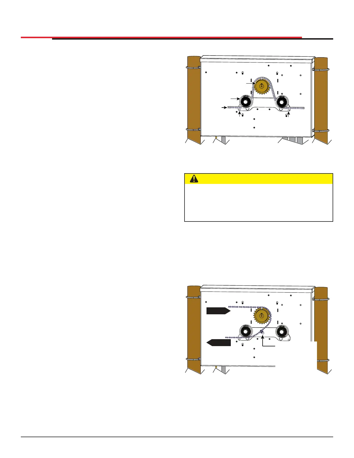
FRONT INSTALLATION
Figure 19. Target Magnet Installation Front
REAR INSTALLATION
Location of target on a rear installation with the
gate in full CLOSE position.
See Figure 20 to view a rear installation for a left
hand gate.
Figure 20. Target Magnet Installation Rear
SPROCKET
IDLER
WHEEL
Keep chain
horizontal
to the
ground
TARGET
SENSOR
(RH GATE)
TARGET
SENSOR
(LH GATE)
CAUTION
When the gate is CLOSED, the target magnet
should stop between the idler wheel and the
roller chain sprocket. The target magnet MUST
NOT enter the sprocket teeth. See Figure 19.
OPEN
OPEN
Chain motion
Position of the
target magnet
when the gate
is fully closed.
INSTALLATION
8. To verify that the operator recognizes the
target magnet, turn off both DC and AC power
switches and watch the display go blank. Then,
turn both switches on. The operator beeps
indicating Limit Relearn Mode. The gate then
travels about 6 inches (15cm) in the open
direction and stops. The buzzer beeps again
and the gate travels in the close direction at a
rate of ½ ft/s until the target magnet passes the
target sensor. The buzzer sounds one last time,
the operator resets, and “GATE CLOSED”
appears on the display.
9. If “LEARN OPEN” appears, then the target
magnet was not detected. Check chain
alignment and make sure the target magnet
passes across the face of the sensor. See Figure
18. Repeat steps 6 - 8. If you are still having
difculty with the operator learning its limits,
re-install the target magnet. See "Establishing
the Open & Close Limits" on page 25.
SlideSmart HD Programming and Operations
2727
MX4435 Rev.G ©2022