SMART DC CONTROLLER
CONNECTING ACCESSORY DEVICES
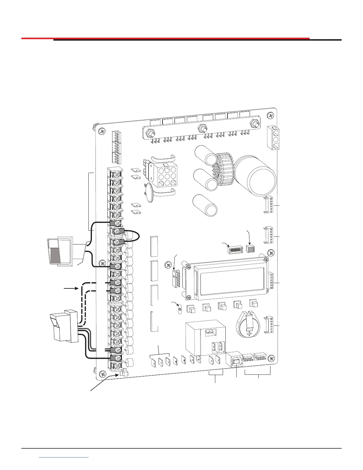
Entrapment Sensor Connections
Devices, such as gate edge sensors and photoelectric beams, must be installed to protect against
entrapment. These secondary external protection devices are required so the gate installation is in
compliance with UL 325 Safety Standards. Figure 54 illustrates how to connect different sensors to the
Smart DC Controller.
Figure 54. Entrapment Sensor Connections
COM
COM
COM
COM
COM
COM
COM
COM
STOP
OPEN
RADIO
CLOSE
OPEN
OPEN
PARTIAL
SENSOR
2
SENSOR
3
SENSOR
1
EXIT
LOOP
BLOCK
EXIT
IN OBS
LOOP
OUT OBS
LOOP
EYE
COM
SENSOR
COM
+ 24 V
EMERG
OPEN
SHOW
LEDs
COMMON
TERMINALS
HY-5B
FREE EXIT
HY-5B
INSIDE LOOP
HY-5B
OUTSIDE
LOOP
HY-5B
CENTER
LOOP
RS-485
COMMUNICATION
USB
PORT
USER RELAY 1
Electro-mechanical
USER
RELAY
2
Solid state
24VDC
24VDC
12VDC
12VDC
Access controls
Photo eye
(Ex. Card reader, keypad)
4-wire connection:
Power COM/+24V
SENSOR COM
Relay COM
EYE OPEN or CLOSE
(depending on function)
Photo eye N.C.
connects to either
Sensor 2
or Sensor 3
Press button to
light active inputs
Master/Slave
Connections
COM
B
A
DUAL GATE
COM
OPEN
+24V
RADIO
OPTIO NS
S1
COM
NO
USER2
DC
Red LED
heart
beat
indicates
processor is
working
RS485
ethernet
RS232
Multi-colored LED
indicates power
and gate status
SlideSmart HD Programming and Operations
7272
support.hysecurity.com