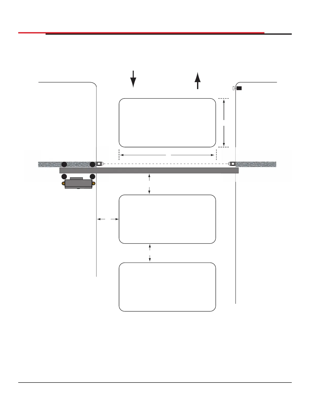
Figure 65. Vehicle Detectors and Loop Layouts for Slide Gates
B
ENTER
EXIT
OUTSIDE
OBSTRUCTION
LOOP
A
ACCESS CONTROL DEVICE
(Card reader, etc.)
PUBLIC SIDE
This layout illustrates a
bi-direconal traffic system with
controlled access entry (card
reader, radio control, etc.) and a
free exit loop. The gate’s closure
me is determined by the number
of seconds entered in the
CLOSE TIMER display found in the
User Menu. The mer to close
starts when all loops are clear.
The mer is adjustable from
1 to 99 seconds.
For a single-direconal system,
the FREE EXIT loop is not needed.
For a sing
e-direcona
system,
e FREE EXIT
oop is not needed.
SECURE SIDE
C
D
E
FREE EXIT
DIMENSIONS
A = 6 to 20 (2 to 6m)
B = 6 to 8 (2m to 243cm)
C = Maintain 4 (122cm)
D = Maintain 5 (152cm) between loop
and edge of roadway. No vehicle can pass
through such a small area and escape detecon.
E = Located for convenience of use.
INSIDE
OBSTRUCTION
LOOP
SENSOR AND ACCESSORY CONNECTIONS
SlideSmart HD Programming and Operations
8585
MX4435 Rev.G ©2022