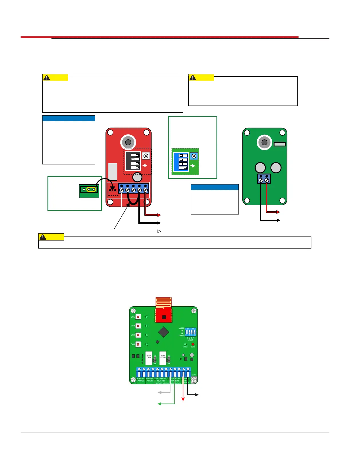
SENSOR AND ACCESSORY CONNECTIONS
After programming the sensor inputs in the installer menu or during initial startup, the appropriate type
and number of sensors will need to be connected. Figure 67 below shows the wiring and dip switch
settings of an EMX-MON photo eye (typical thru-beam wiring). A retroreective photo eye will be similar
and only have wiring similar to the receiver of the thru-beam photo eye.
Figure 67. EMX-MON Photo Eye Wiring
An Edge Sensor can be either hardwired through an adapter module (Hy2NC) or a wireless transmitter/
receiver combo (WEL-200 or iGAZE RE). Figure 68 below shows the wiring and dip switch settings of a
WEL-200. For more information and wiring diagrams of other recommended sensors see the “HySecurity
External Entrapment Sensor Wiring Guide”.
Figure 68. WEL-200 or iGAZE RE
EMX IRB MON
Photo Eye Receiver
POWER INPUT
TRANSMITTER
IRB-325-MON-TX
All external entrapment protection sensors must be NC sensor
outputs and wired to the Sensor Com terminal for monitoring
and powering purposes. The sensor is actively powered until
the gate reaches the open limit where the monitored check is
performed.
Connect all contact and non-contact sensors to same
power source. Example, Do NOT connect photo eyes
to +24VDC and gate edges to +12VDC. Incompatible
power connections result in a FAULT 2 in the display.
NOTICE
DIP switches must be
set as shown, otherwise
the photo eye will not
operate correctly. Note
that older green receiver
PCBs are set differently
from the newer red PCBs.
CAUTION
CAUTION
CAUTION
NOTICE
Wire transmitter power
input only to power
supply common (not
Sensor Common).
EMX IRB MON
Photo Eye Transmitter
Jumper between
COM & Power Common
NC Relay to Sensor 1
Power Common to
Sensor Common
Red
+24V
+24V
Black
White
If you receive an Alert, "!ACTION BLOCKED" "Photo Eye Open" PEO or "Photo Eye Close" PEC, take steps to align the photo eye.
4321
C E
COMNC NO
ON
POWER
RECEIVER
IRB-MON
RX
4321
ON
For GREEN PCBs
(before 06/2020),
set DIP switches
as shown below.
2 = OFF
4 = OFF
3 = ON
1 = OFF
1 = OFF
2 = OFF
3 = OFF
4 = ON
OLDER GREEN RX PCB
OLDER GREEN RX PCB
Power Common
to Power Common
Red
Black
10K
For green RX
PCBs,ensure
jumper is
removed from
two left 10K pins.
SENSOR 1,2, or 3
SENSOR COM
SENSOR COM
+24V
EMX WEL-200 Wireless Edge Receiver
Dip Switch Settings determine which relay
activates when the associated edge is tripped.
SlideSmart HD Programming and Operations
8787
MX4435 Rev.G ©2022