PC Board Quick References
Manual # 42-02-1P28 A3 6-35
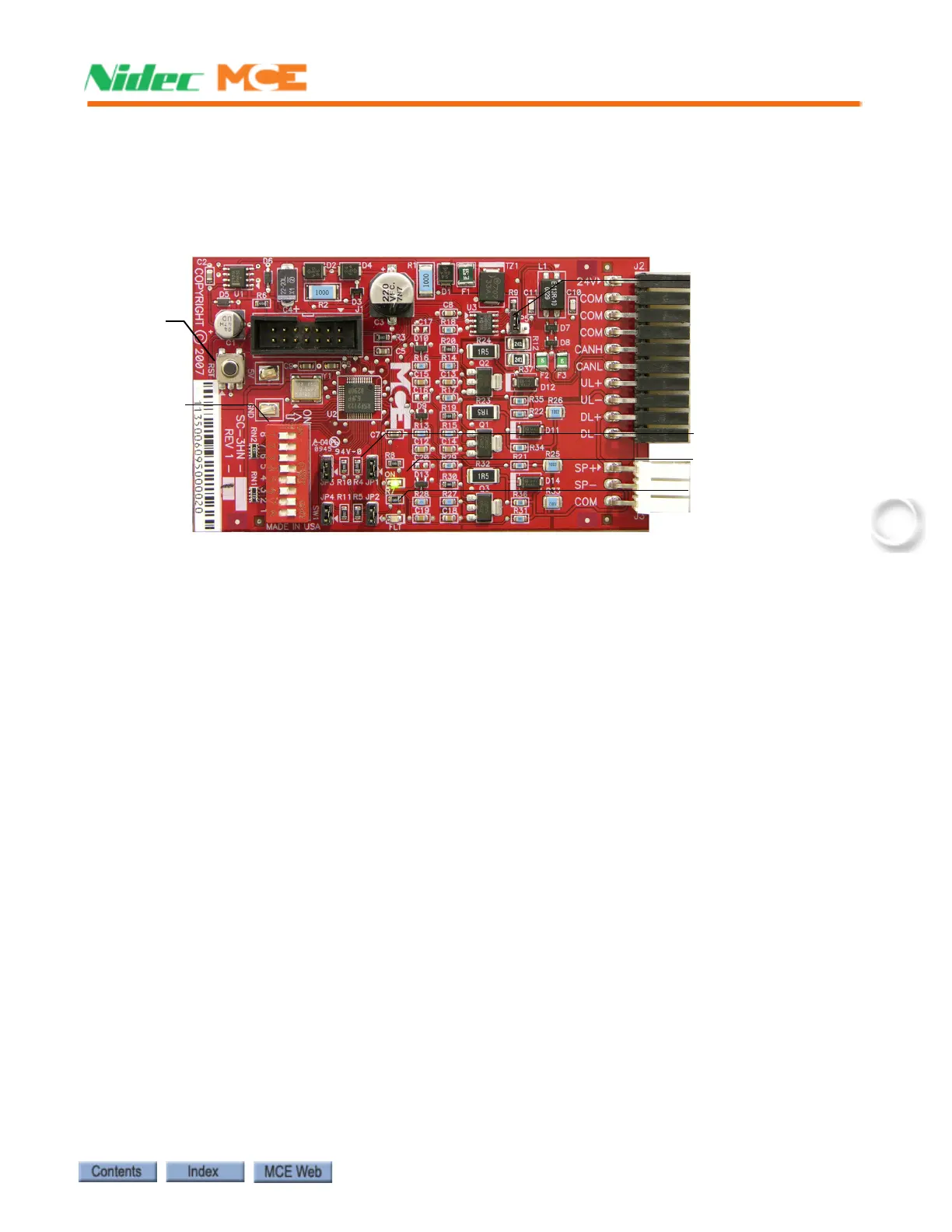
SC-3HN Three Input Serial Hall Call Node Board
The SC-3HN board is used to provide serial hall calls for Motion systems. The SC-3HN provides
analog inputs and outputs for the hall call buttons and LEDs and a CAN connection to the group
or controller. Refer to the drawings package for connection instructions to your fixtures.
Figure 6.3 SC-3HN Three Input Serial Hall Call Node Board
Call Bus Conditions
Make connections as shown on the drawings for the particular job.
• Group: Eight risers are supported; four Main and four Auxiliary.
• Controller: Four main risers are supported.
• Each hoistway wire drop consists of a twisted pair for signals and one wire each for 24V
power and common. A wire drop can support more than one riser.
• Settings on each SC-3HN board determine which riser it belongs to, its floor address, and
whether it is associated with the Front or Rear car entry.
• SC-3HN boards with the same floor address and entry association will register the same
call and light indicators. Each must have a different riser ID but within the same riser
group (Main or Auxiliary).
• Main risers A - D use riser IDs 7 - 4. Auxiliary risers A - D use riser IDs 3 - 0.
General Installation
All SC-3HN connections are at one end of the board. One board is installed in each hall call
panel electrical box. The board is shipped in an anti-static bag.
1. Make connections to the hall call buttons and indicators.
2. Make connections to the signal/power drop. (See following page.)
3. Set floor number and door (F/R) location, 6-37.
4. Set riser assignment, 6-37.
5. Last board on wire drop only: Place a jumper on JP5. All other boards: Ensure jumper
NOT placed across JP5 pins, 6-20.
6. Insert board in anti-static sleeves and tape closed using supplied ESD sticker.
7. Tuck bag/board into electrical box and reinstall hall call.
Processor
Reset
Entry / Floor
Address
Riser Identification
JP5, CAN Bus termina-
tion. Place across pins
ONLY on last board
connected to a wire
drop.
ON LED, green
FLT LED, red