Startup - Inspection Operation
3-2 Manual # 42-02-1P28 A3
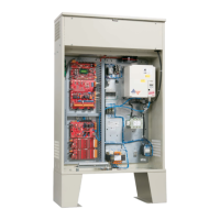
Check for Shorts to Ground
Check for shorts to ground before powering up the system. Set the meter for resistance mea-
surement (100 to 200 ohm range). Take all measurements with respect to the 1-bus, which is
also referred to as the system common or common elsewhere in this manual.
A short to ground is defined as having a resistance of less than 20 ohms between the 1-bus
(common) and the terminal being checked.
1. Remove fuse F2 from the fuse holder in the individual car controller cabinet. If the sys-
tem is a duplex controller, refer to the job prints and remove the fuse that powers termi-
nals 2H (Hall Call Power Bus) and/or 2FS (Fire Service Bus). Check for shorts to ground
on the 2H and/or 2FS terminals.
2. Check for shorts to the ground on all screw terminals on the bottom of the HC-CTL-2
Control board. Terminal 1 bus is the only terminal that should be grounded.
3. Check for shorts to ground on all terminals on the HC-UIO-2 Universal I/O board.
4. Check for shorts to ground on the door operator terminals. Consult the job prints to
determine which fuses to remove.
Before Applying Power
These instructions assume adequate electrical troubleshooting experience. Follow the proce-
dure carefully. If the elevator does not respond correctly, check the circuits according to your
ability. Proceed cautiously. Read these instructions fully to become familiar with the procedure
before starting the work.
1. Unplug the screw terminal blocks from the HC-UIO-2 Universal I/O boards by moving
the blocks toward the right. This is done to avoid damaging the boards through an acci-
dental shorting of the output devices to a power buses (terminals 2, 2S, or 2L) during
the initial power up of the system.
2. Verify that all circuits are wired to the controller properly.
3. On the HC-CTL-2 Control board, verify that the MACHINE ROOM INSPECTION switch
is in the INSP position.
4. On the HC-CTL-2 Control board, verify that the HOISTWAY DOOR and CAR DOOR
BYPASS switches are in the OFF position.
5. Verify that the Main Line Power Supply voltage matches the controller’s designed volt-
age. Refer to the job prints provided with the controller and the silver label on the solid
state starter (if used).
 Loading...

