Hoistway Control Equipment Installation
Manual # 42-02-1P28 A3 3-9
Hoistway Control Equipment Installation
This section covers the recommended procedures for installing the LS-EDGE landing systems.
LS-EDGE Installation
The LS-EDGE positioning system uses hall-effect sensors and perforated steel tape to report
position as the car moves through the hoistway. 5.5-inch magnets are used at each door zone;
one row for front openings, a second for rear openings. LS-EDGE is also available in a NEMA
4x/12 configuration that uses stainless steel hoistway materials and a sealed sensor head.
The system uses capacitor-stored power and non-volatile memory to retain position informa-
tion in the event of a power failure, continuing to capture information for 10 seconds after
power loss and storing the final reading for use after power restoration. The LS-EDGE system
may be used with MCE iControl, Motion, or Motion 2000 TS elevator controls.
The LS-EDGE kit contains the sensor head assembly, an L-bracket to mount the sensor assem-
bly to a Unistrut channel that is in turn attached to the elevator cab (Unistrut channel to eleva-
tor cab not provided), steel tape, top and bottom steel tape hanger assemblies, the required
number of door zone magnets, and the CAT-5 electrical cables required to connect the sensor to
the interface board.
Depending on applicable code, you may have to route electrical connections through conduit. If
so, we recommend minimum 3/4-inch flex so that the modular connectors can slide through
without binding. Perforations for cable tie wrap connection are provided on the RJ-45 plug-end
of the sensor head.
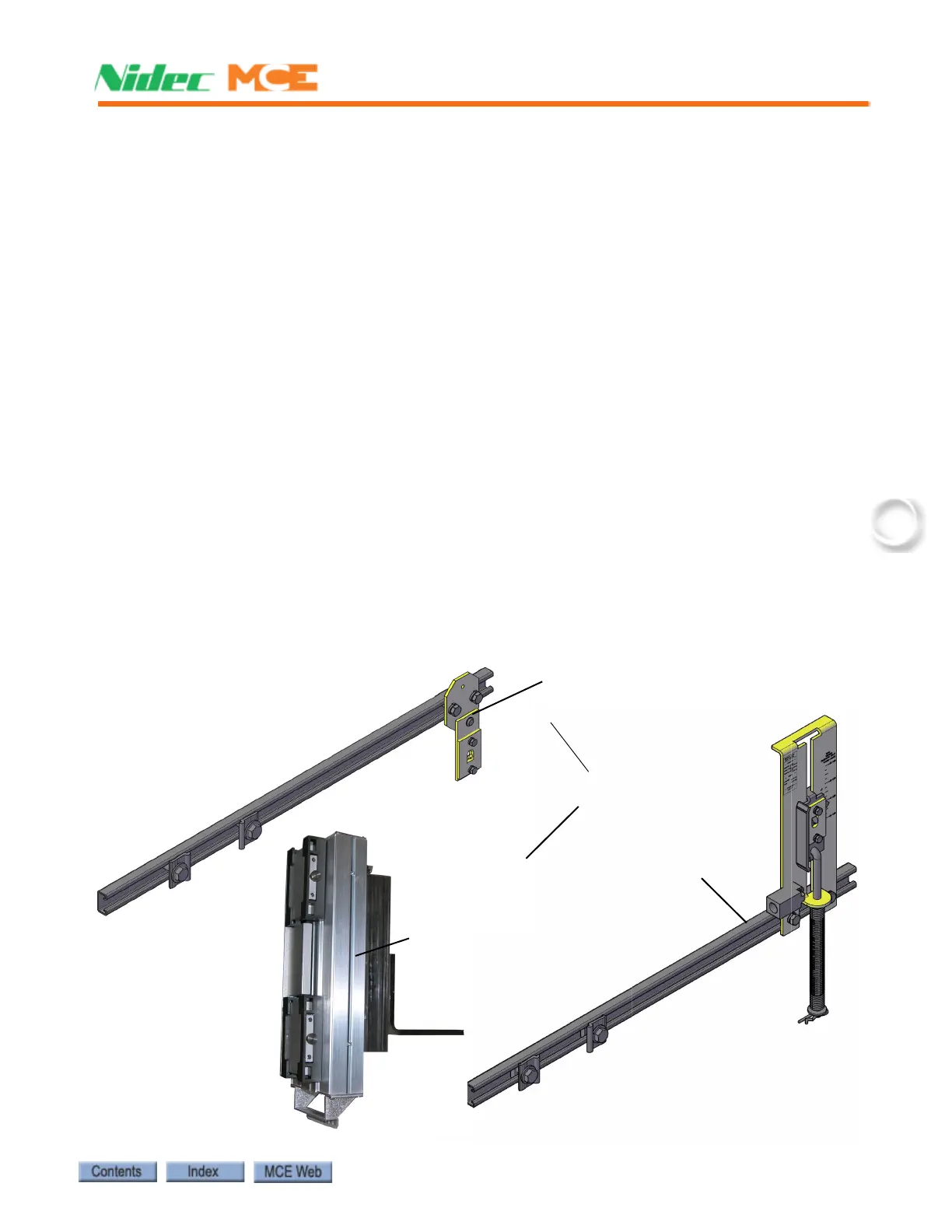
Figure 3.3 LS-EDGE Components
Together, these are assembly
LS-TAPE MNT-EDGE
Steel tape, magnets & connecting cables not shown
Top hanger assembly
(diagonal brace not shown)
LS-TAPE MNT TOP-EDGE
Sensor assembly
LS-EDGE
Bottom hanger assembly
LS-TAPE MNT BOT-EDGE