Applying Power
Manual # 42-02-1P28 A3 3-3
Applying Power
Initial Adjustments and Power Phasing
When performing the following steps please exercise extreme caution to prevent personal
injury or damage to components and equipment. Have someone stand by the main power dis-
connect switch during the following phases of the start up procedure for added safety:
• First time power is applied to the controller
• First time an attempt is made to move the car
1. Check the line side of the Main Power Disconnect switch to verify that all three legs are
at the correct voltage.
2. Reinstall fuse F2 to enable the primary controller relay voltage.
Verify Proper Pump Motor Rotation
1. Verify that the pump motor wiring has been installed per the job prints.
2. Turn ON power to the controller by closing the Main Power Disconnect switch.
3. Check the pump motor rotation using the method that is appropriate for the type of
starter installed on the controller:
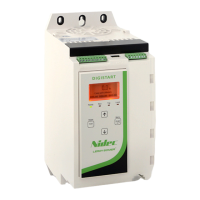
• Solid State Starter: Take a jumper from 2 bus and briefly apply it to the motor run
screw terminal on the solid state starter and observe the motor rotation.
• Y-Delta contactor: Activate the Y contactor and observe motor rotation.
• Across the line (ATL) contactor: Activate the A contactor and observe motor rota-
tion.
4. Faults may occur while performing this operation. To clear latching faults, place the car
on Machine Room Inspection and press the FLT RST button on the HC-CTL-2 Control
board.
5. If the motor rotation is reversed, switch any two of the three leads at the Main Discon-
nect switch.
6. If an RP (Reverse Phase) sensor is provided and the sensor contact does not close when
power is applied to the controller (indicated by a light on the sensor that comes on when
phase rotation is correct), then 2 of the 3 AC wires that are connected to the RP sensor
may need to be switched.
7. To provide an immediate stop once direction is released, set the SOFT STOP DELAY
TIMER in System Control Parameters menu options to 0 (zero).
The SLOW INSPECTION SPEED option determines if the car will run at high or low speed on
In-car, Cartop, or Machine Room Inspection or Hoistway Access. If the car contract speed is
greater than 150 fpm, the SLOW INSPECTION SPEED should be set to YES. (CONFIG 02 >
SYSTEM CONTROL PARAMETERS)
 Loading...

