General Wiring Guidelines
Manual # 42-02-1P28 A3 2-9
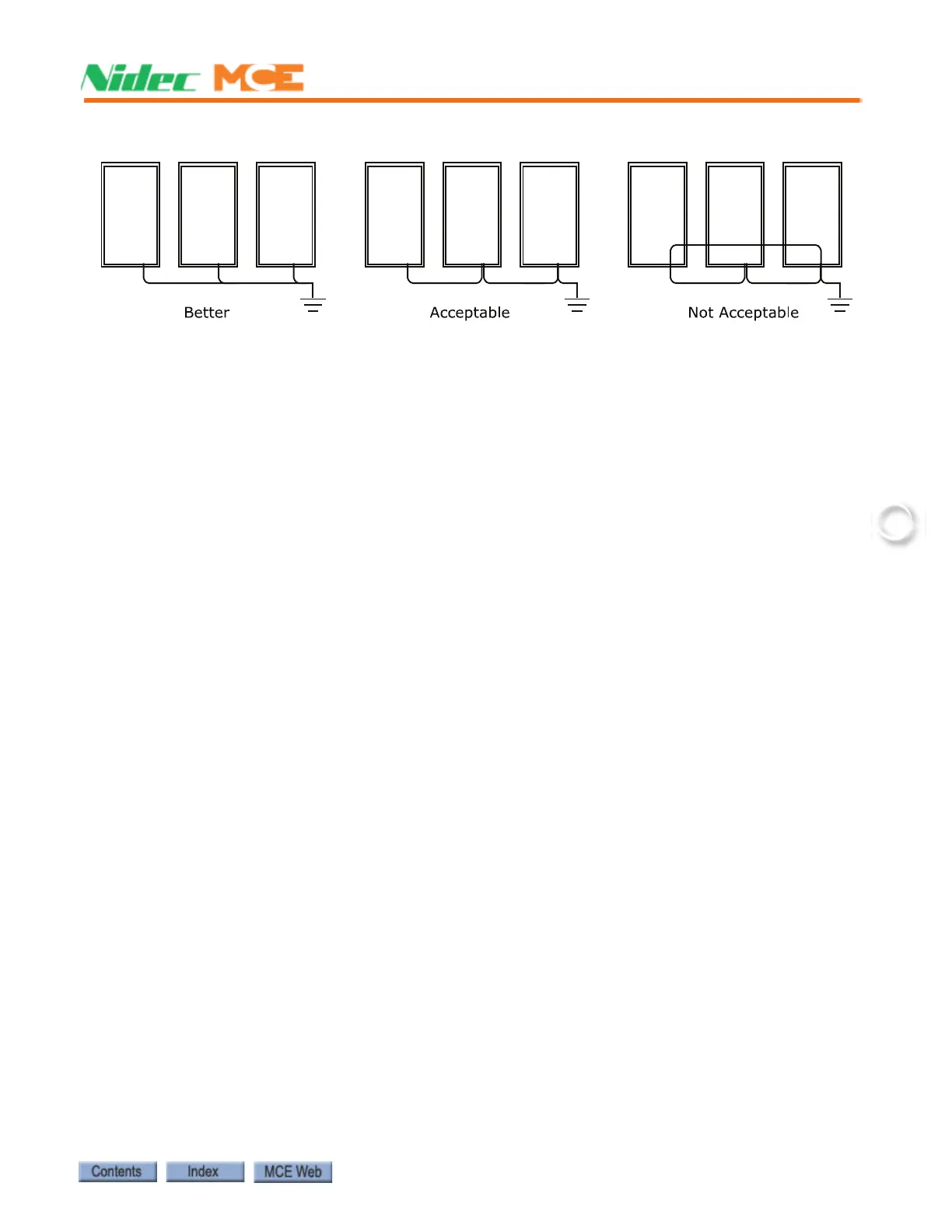
Figure 2.1 Ground Wiring to Controller Cabinets
• Direct solid grounding must be provided in the machine room to properly ground the con-
troller and the motor. Indirect grounding, such as the building structure or a water pipe,
may not provide proper grounding and could act as an antenna radiating RFI noise, thus,
disturbing sensitive equipment in the building. Improper grounding may also render an
RFI filter ineffective.
• The conduit containing the AC power feeders must not be used for grounding.
Main AC Power
Main AC power supply wiring size must be determined by the electrical contractor. Proper
motor branch circuit protection must be provided according to applicable electrical codes in the
form of a fused disconnect or circuit breaker. Each disconnect or breaker must be clearly
labeled with the elevator number.
Pump Motor Wiring
Connect the pump motor for the proper configuration shown on the wiring diagrams. Connect
the pump motor leads to the proper terminals on the controller.
Low Voltage Signal Wiring
Low voltage signal wiring includes all 24-volt inputs. The inputs on the I/O boards can be
turned on with as little as 12 Vac. If the signal wires are run along side the 240 Vdc door opera-
tor wiring, an induced 12-volt spike is very likely to occur. Keep low level signal wiring at least
four inches from high power wiring to avoid false signal firing. If this is not possible, and the
low level wiring must cross the high power wiring, the two should cross at a ninety-degree
angle.
Traveling Cable Wiring
When laying out traveling cable wiring, it is always best to have the low voltage signal wiring
multiple layers away from any 14-18 AWG power wires and high voltage signal wires.
The number of required wires and twisted pairs is documented in the job prints. The travelers
are also identified by the use of yellow terminals in the top of the car junction box. Always allow
10% or more additional wires for spares.
On lower rise cars, it is often beneficial to run the traveling cable directly to the top of the car
junction box. This avoids terminating traveler wires at the midway and at the under-car junc-
tion box.