The Computer
5-2 Manual # 42-02-1P28 A3
The HC-MPU-2-TS Main Processor Unit
The computer on the Motion 2000 TS Hydraulic Elevator Controller has been designed for easy
communication between the mechanic and the controller and between the controller and other
computers or data terminals. The computer is used for diagnostic troubleshooting and for pro-
gramming the controller.
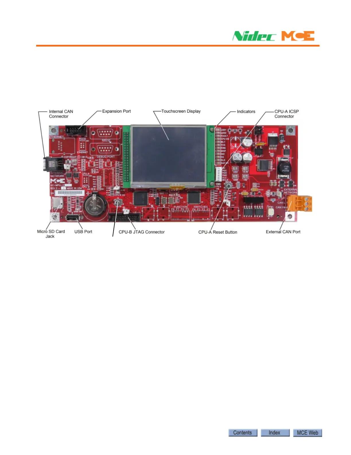
Figure 5.1 HC-MPU-2-TS Main Processor Unit
Figure 5.1 shows the indicators, push buttons and terminals on the main processor unit.
Indicators
CPU-A, CPU-B When steadily illuminated, these LEDs show that the computer is func-
tioning normally and completing its program loop successfully. Pressing the RSTA button will
cause the CPU A ON LED to turn off and stay off while the RSTA button is depressed. Pressing
the RSTB button will cause the CPU B ON LED to turn off and stay off while the RSTB button
is depressed. The computer is equipped with a watchdog feature that will shut down the con-
troller if the program loop cannot be completed (software system failure). If the COMPUTER
ON light is OFF or flashing continuously, it means that the computer board is malfunctioning.
Status Indicators These lights show the status of the elevator. Table 5.1 shows a list of
these lights and their meanings.